TC2MHR series
Telecentric lenses for sensors up to 1”
Overview
Models
Downloads
Related
Resources

Magnification
0.053 - 0.768 x
Classic
Key advantages
- Wide image circle for sensors up to 1”
- Excellent resolution and low distortion
- Simple and robust design for industrial environments
- Detailed test report with certified optical parameters
- Easy phase adjustment
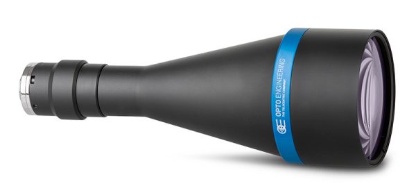
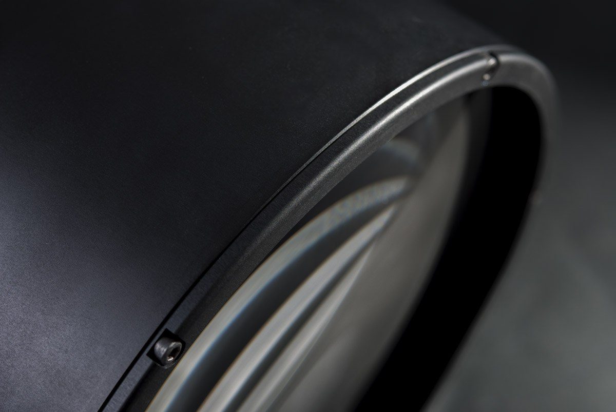
TC2MHR series features high-resolution telecentric lenses designed for sensors up to 1" and is the perfect choice for advanced metrology applications. Our TC2MHR series ensures unmatched resolution, low distortion and homogeneous image quality while offering the best performance-to-price ratio.
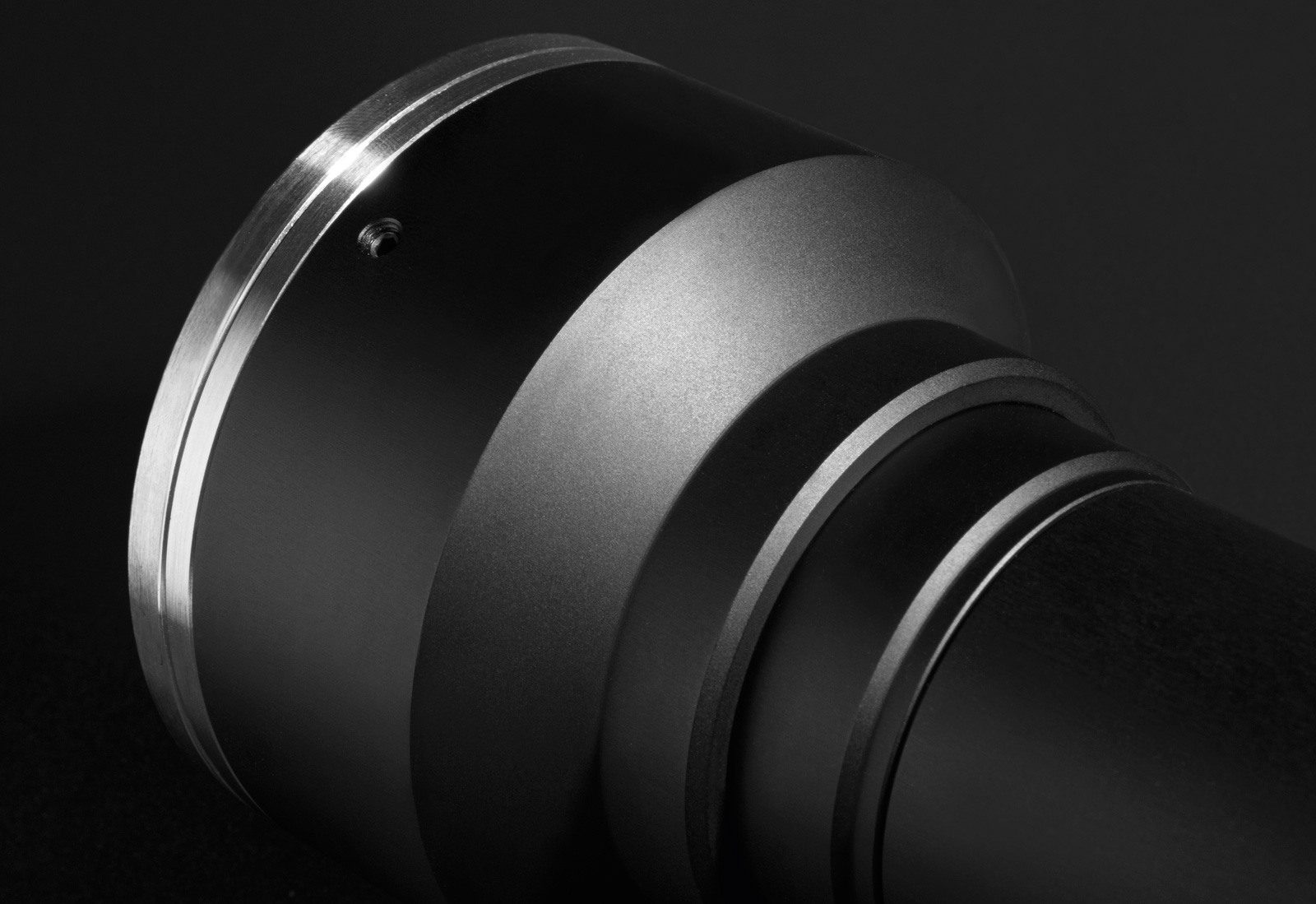
Thanks to their compact and robust design, TC2MHR lenses can be easily integrated in industrial environments. Additionally, the set screws positioned in the eyepiece allow to easily adjust the camera phase.
Discover more
Please wait
Unable to process your request
Back to models
Filters
Close
Reset Filters
Notes
- Working distance: distance between the front end of the mechanics and the object. Set this distance within +/- 3% of the nominal value for maximum resolution and minimum distortion.
- Working f-number (wf/N): the real f-number of a lens in operating conditions.
- Maximum angle between chief rays and optical axis on the object side. Typical (average production) values and maximum (guaranteed) values are listed.
- Percent deviation of the real image compared to an ideal, undistorted image. Typical (average production) values and maximum (guaranteed) values are listed.
- At the limits of the depth of field, the image can still be used for measurements. For a very sharp image, however, only half of the depth of field should be considered. Pixel size used for calculation is 3.45 μm.
- Object side, calculated with the Rayleigh criterion with λ= 520 nm
- Indicates the availability of an integrated camera phase adjustment feature.
- Measured from the front end of the mechanics to the camera flange.
Ordering information
It's easy to select the right lens for your application: our models are coded as TC2MHRyyy-x where yyy refers to the width of the object FOV in mm and -x refers to the mount option.
Customized mounts are also available upon request.
Customized mounts are also available upon request.
Back to models
Video gallery

What is a TC and why is it useful?

How to pick the right telecentric lens

Common applications of TC lenses

Industry focus for Telecentric lenses
Other videos (in English)
Mechanical

Automotive


Glass & pharma

Electronics