Horus
Windows OS desktop application for optical measurement
Key advantages
- Very accurate calibration and measurement over the entire field of view
- Live measurement and tracking of objects placed in any position
- Very intuitive interface, consistent with most CAD environments
- Flexible, configurable and open to the integration with other devices
Horus is a metrology software application ensuring unparalleled system measurement accuracy thanks to its state-of-the-art calibration algorithms and protocols.
Horus is a very intuitive and user-friendly software allowing for real time measurement of parts: its interface and procedures are designed to closely match a traditional CAD software approach thus ensuring a quick and easy check of the measurement results.
Parts are automatically recognized and tracked over the entire field of view with no need for reconfiguring the measurement procedure, while tools for automatic geometric primitives and part geometric construction search make metrology information even more easily available.
An advanced approach to edge detection and system calibration ensures maximum accuracy to your measurement system.
Statistics are really intuitive and easy to use and allow to obtain complete measurement reports and data extraction.
Horus can be easily configured and released independently by machine builders who want to address the specific type of process and needs of their customers.
Moreover, Horus is suitable for customizations of the program interface, of existing program features as well as for the creation of new application-specific features, according to customers' need, including online measurement operations.
Real-world application examples and case histories
| NOTES 1. Available exclusively in combination with an HORUS-FOV-003 Base License. |
||||
| Part number | Description | License Type / Contract | Perpetual | License distribution |
|---|---|---|---|---|
| HORUS-FOV-003 | Windows OS desktop application for optical measurement on USB dongle | Base License | YES | USB dongle |
| HORUS-ADD-001 (1) | DFX manager add-on | Add-on License | YES | USB dongle |
| HORUS-ADD-002 (1) | Circle pattern calibration add-on | Add-on License | YES | USB dongle |
| HORUS-ADD-003 (1) | Screws Metrology add-on (EU version) | Add-on License | YES | USB dongle |
| HORUS-ADD-004 (1) | Gear wheels Metrology add-on | Add-on License | YES | USB dongle |
| HORUS-ADD-005 (1) | Screws Metrology add-on (CN version) | Add-on License | YES | USB dongle |
| HORUS-ADD-006 (1) | O-rings Metrology add-on | Add-on License | YES | USB dongle |
| HORUS-ADD-007 (1) | Photometry add-on | Add-on License | YES | USB dongle |
| HORUS-ADD-008 (1) | Depth of focus add-on | Add-on License | YES | USB dongle |
| HORUS-ADD-009 (1) | Image stitching add-on | Add-on License | YES | USB dongle |
| HORUS-LIB-FOV-003 (1) | Windows OS library to manage Horus FOV projects add-on | Add-on License | YES | USB dongle |
Live measurement
Objects are instantly recognized and measured in real time ensuring very fast measurement operations.

Object tracking by recognition
Synthetic
models of multiple objects can be created from images. The software
recognizes every object in any position and with whatever rotation
within the field of view.
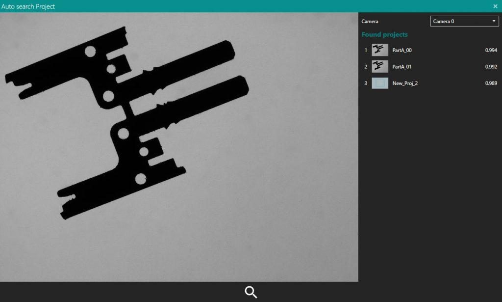
Measurement program auto-search
The software can automatically recognize the object and apply its
specific pre-defined measurement program. Based on the image, the
software searches for all the objects that best fit it, and returns a
list of results.
Self-detection of geometric primitives
Geometric primitives can be either automatically identified or defined by the operator. This allows for the analysis tools to be easily created with a simple click from within a dedicated set-up window.

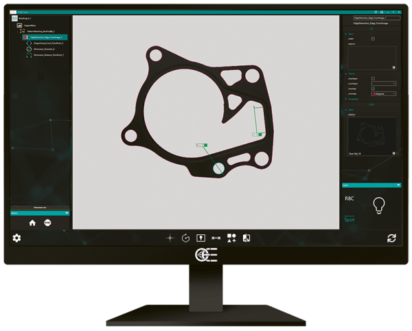
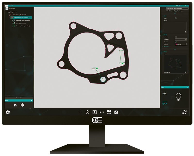
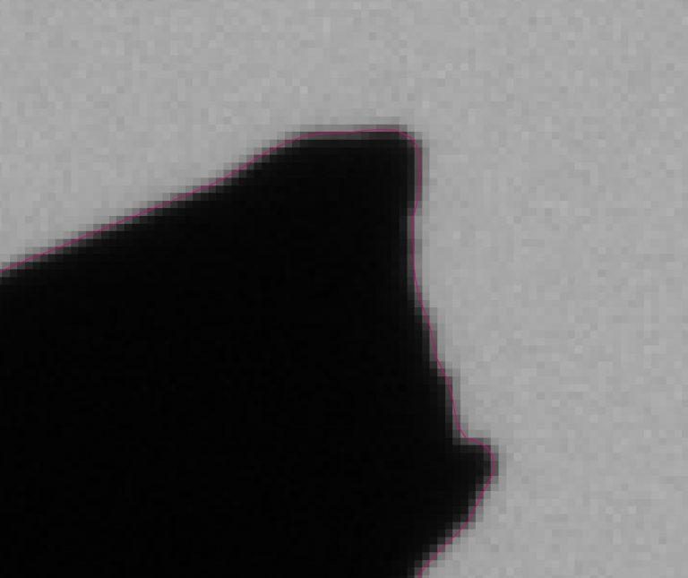
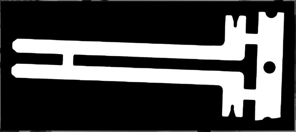
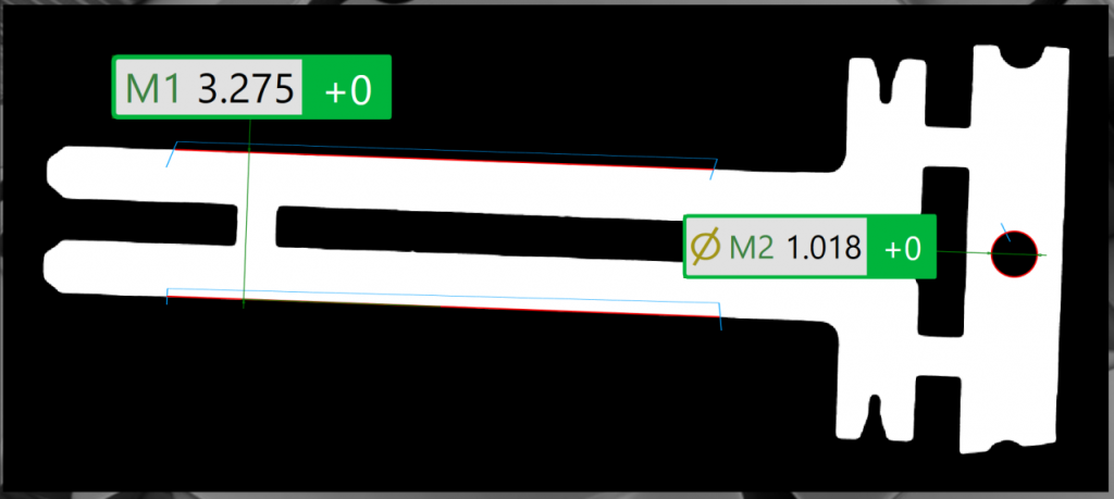
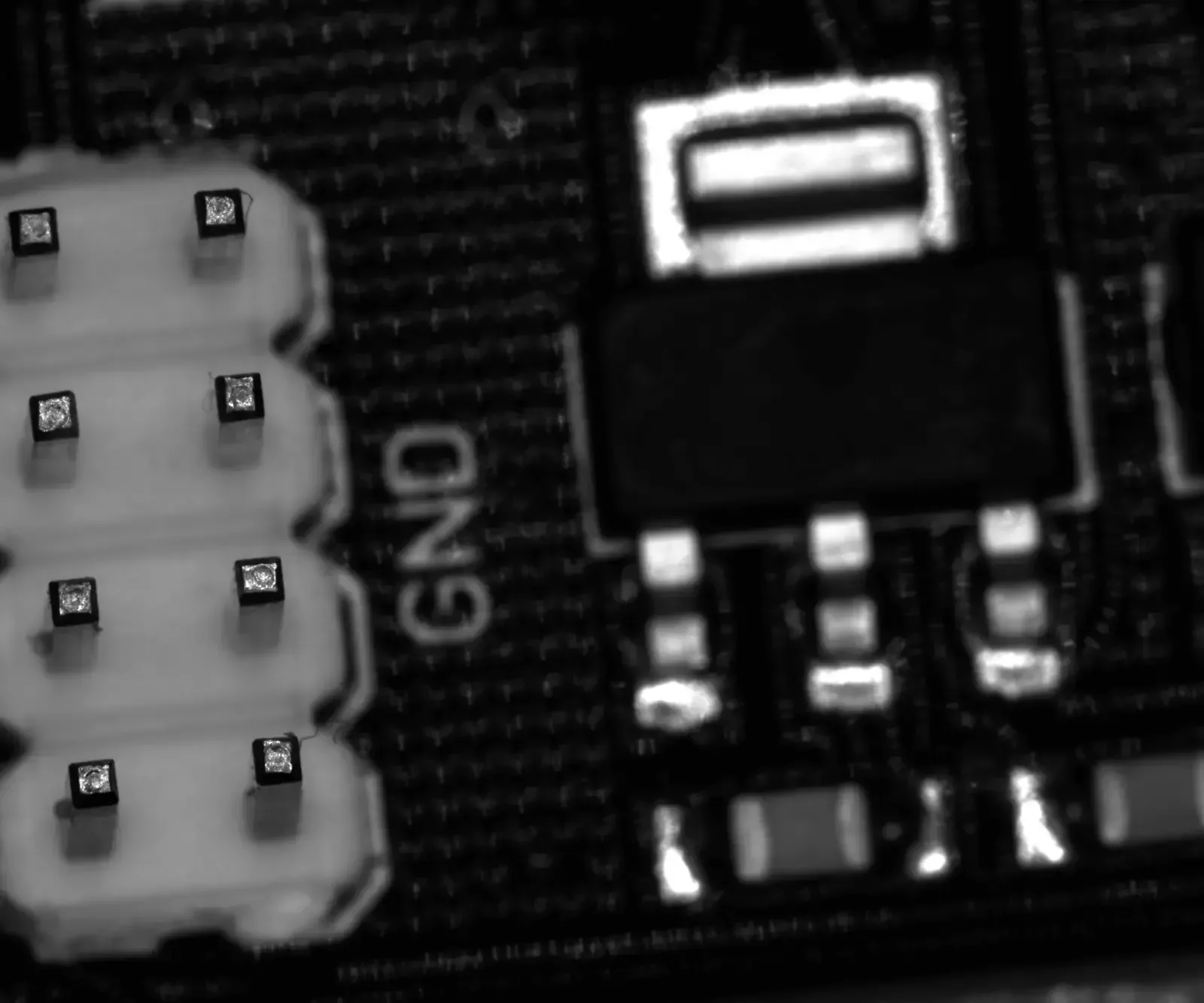
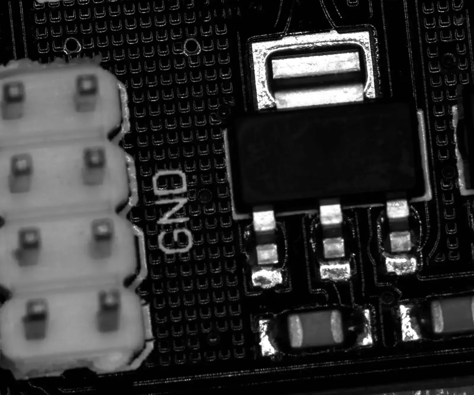
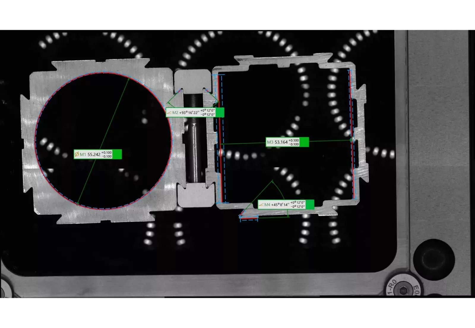
Episcopic measuring tool
This tool is dedicated to measurements on front-illuminated (episcopic) setups. It doesn’t require any time-consuming parameterization and is extremely robust against variations of illumination and contrast. The tool automatically identifies the object primitives, even if scarcely visible or defined by low contrast, in cases where a clear edge extraction would not be easy with standard tools. The resulting measurements are repeatable and stable.
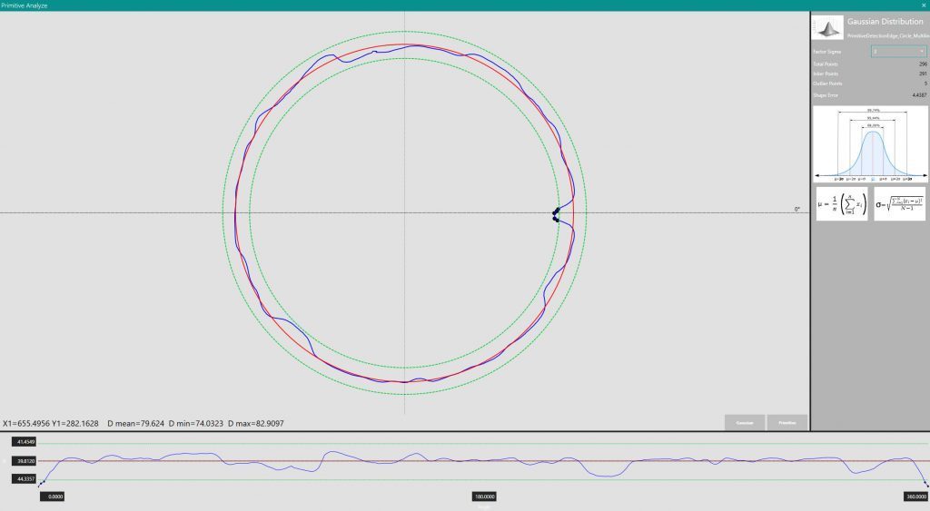
Accurate control of fitting primitives
Geometric primitives can be point-by-point controlled by means of statistical tools: point distribution can be checked and used to apply filtering process.
Creation of part and/or assembly program
With Horus it is possible to create multiple project files related to the same part. With this method, particularly indicated for multi cameras systems, you can use multiple projects to analyze the same part in different ways, e.g. front view vs top view or side view.
Statistical reports
The measured values are stored in a database that is configured so that historical and statistical trends can be easily reviewed and consulted. Data can be read, modified, exported in CSV format and the reports can be printed. Other export formats can be developed upon request.

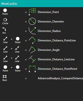
Simple features creation tool
Creating dimensions, geometric shapes and any other feature is always guided by descriptions and commands suggested graphically in the user interface. Horus can easily manage either typical elements of CAD modelling (intersections, axes, perpendicularity and parallelism, etc.) or geometric nominal values and tolerances through automatic or tool-aided creation of dimensional data boxes.
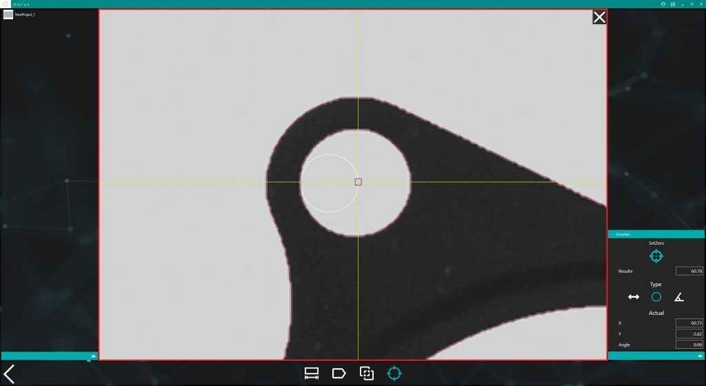
Crosshair
The crosshair function for manual measurements allows for the analysis to be made also in situations where the processing is difficult due to part/environmental conditions and where automatic tools might not be enough. As always, the graphical user interface helps in defining distances, diameters or angles.
Advanced image edge management
Black-to-white transition curves are analyzed and the most appropriate edge placement and position correction is applied using sub-pixel accurate edge extraction. Different edge corrections can be applied to ensure maximum results and to compensate material and shape refraction.
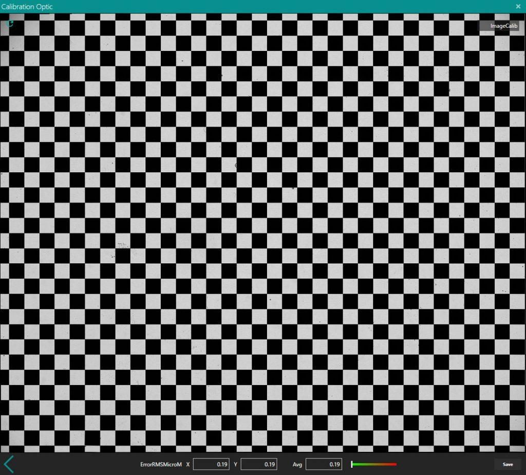
Advanced system calibration and optimization
A complete set of advanced tools ensure the calibration and optimization of all the variables of the system in order to achieve high accuracy and consistency. Our calibration procedures ensure maximum measurement constancy over the entire field of view, thus making the measurement much less sensitive to object displacement over the field of view. Lens calibration, light alignment, object plane control and adjustment and autofocusing tools combined with a motorized vertical axis ensure optimum performance by minimizing any measurement issues arising from system asymmetry or misalignment.
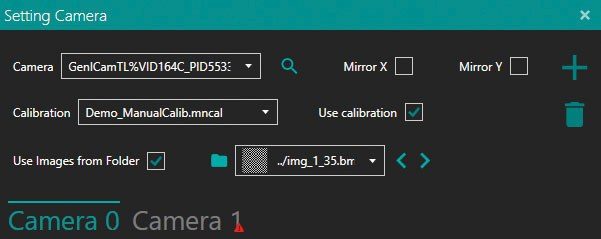
Flexible camera interface
Horus supports cameras compliant with GeniCam, GigEVision, USB3 Vision and other main camera standards. Other types of cameras can be very easily integrated upon request.
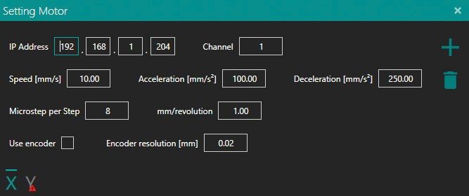
Motorized axis and light control integration
Horus is compatible with pre-defined motion control units. For best image focusing, the Z-axis is driven and controlled by the application. For CNC-type measurement machines, readout, calibration and control of an XY-stage, can be easily integrated through proprietary or customer specific axis control, together with a fourth axis providing the rotational degree of freedom. Non-standard motion controllers can be integrated upon request.
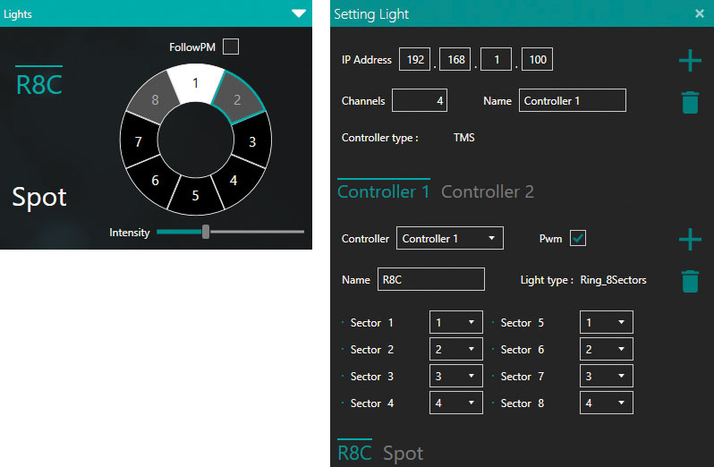
Smart light control integration
Horus is compatible with pre-defined illumination control units. The light control tool manages illuminators and specifically ring lights with 1, 4 or 8 sectors. A smart control of multi-sector ring lights is possible, where specific sectors are turned on depending on the part orientation and location on the FoV. Non-standard illumination controllers can be integrated upon request.
Touch support
Horus is designed to be used with ease even without keyboard or mouse. All menus, functions, filters and tools are right at your fingertips.

Multi language support
Horus comes in 5 different languages: EN, DE, FR, IT, ZH.

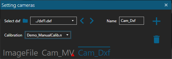
DXF Camera
The DXF Camera plugin allows to upload a .dxf file from the local storage and transform it into an analyzable image in Horus. Technical applications become much easier and more time-saving with this tool.
As shown in the pictures, first a .dxf is imported and then the analysis is performed using quotes, tolerances and so on.
As the other tools and features in Horus the access is simple and clear: from the camera setting, select dxf camera and the .dxf file that has to be loaded.
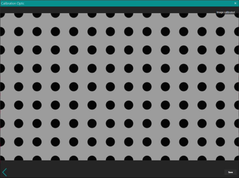
Circle calibration
Instead of using a checkerboard calibration, with this feature, it is possible to use a plate with circles as a calibration reference, enlarging the possibility of the calibration.
In the example, it is possible to check how the calibration is performed and the adjustment done by the software.

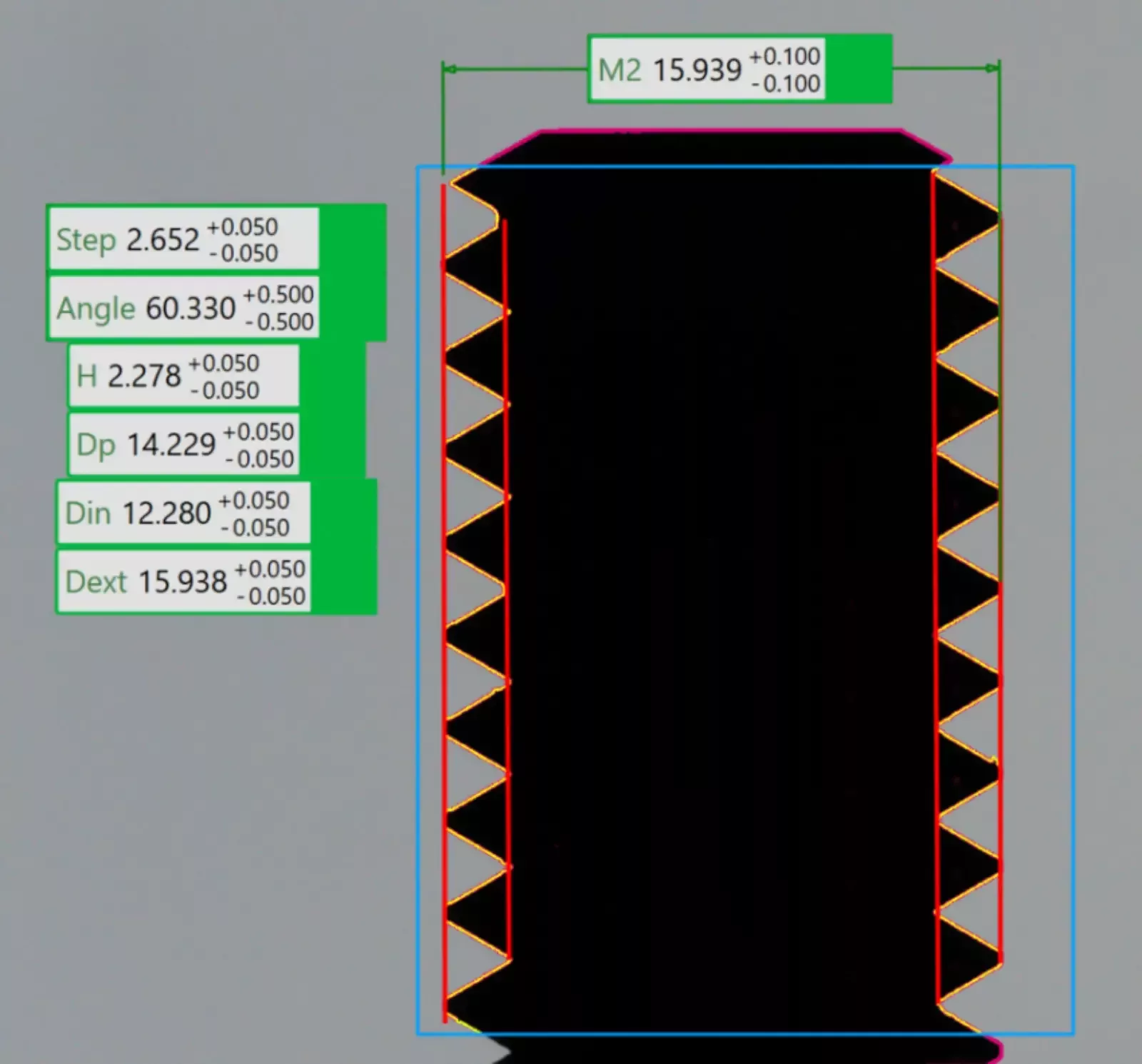
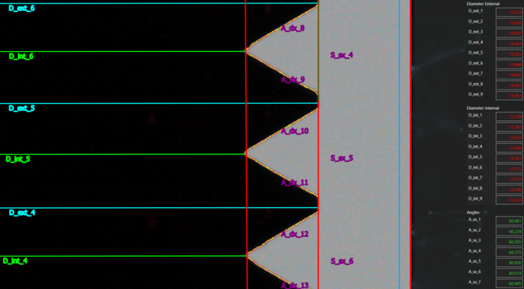
Thread ISO
The thread ISO tool has the capability to visualize steps, angles and diameters (internal and external) of a thread just by selecting an area containing the object.
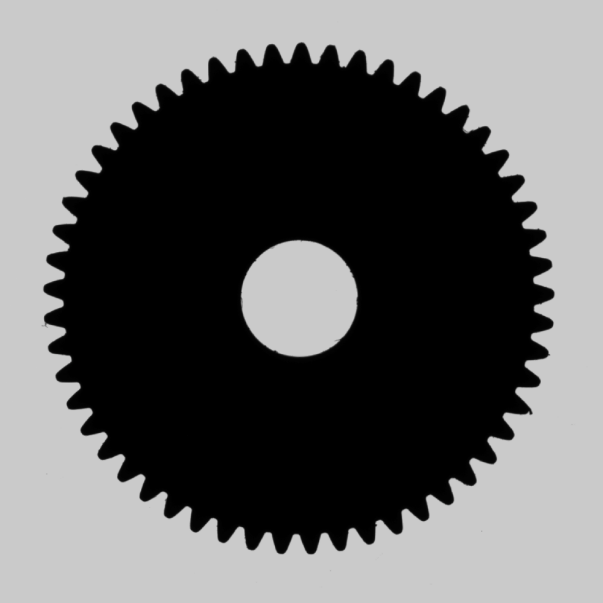
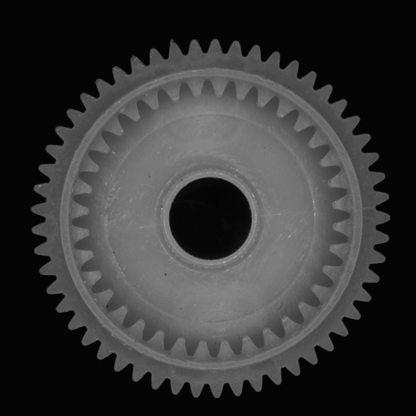
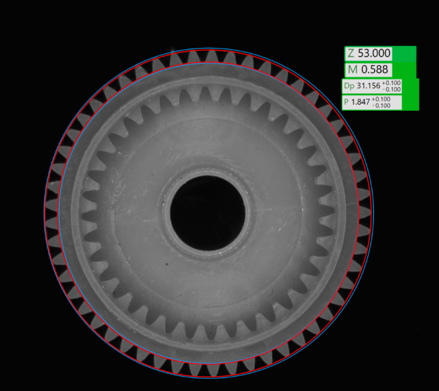
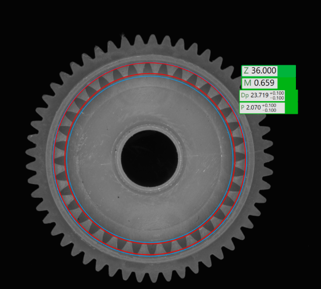
Gear
In the detail, it is possible to see how the object is handled by the analysis. Each recognized element is assigned a name, and a value corresponding to the assigned name is entered in the side menu.
Once a gear is detected, the tool shows by default the main parameters into several labels allowing a fast and precise insight.
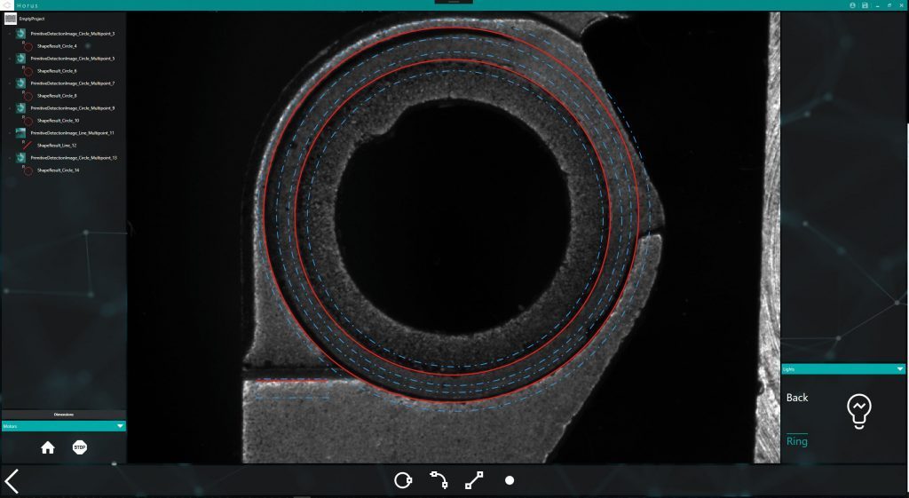
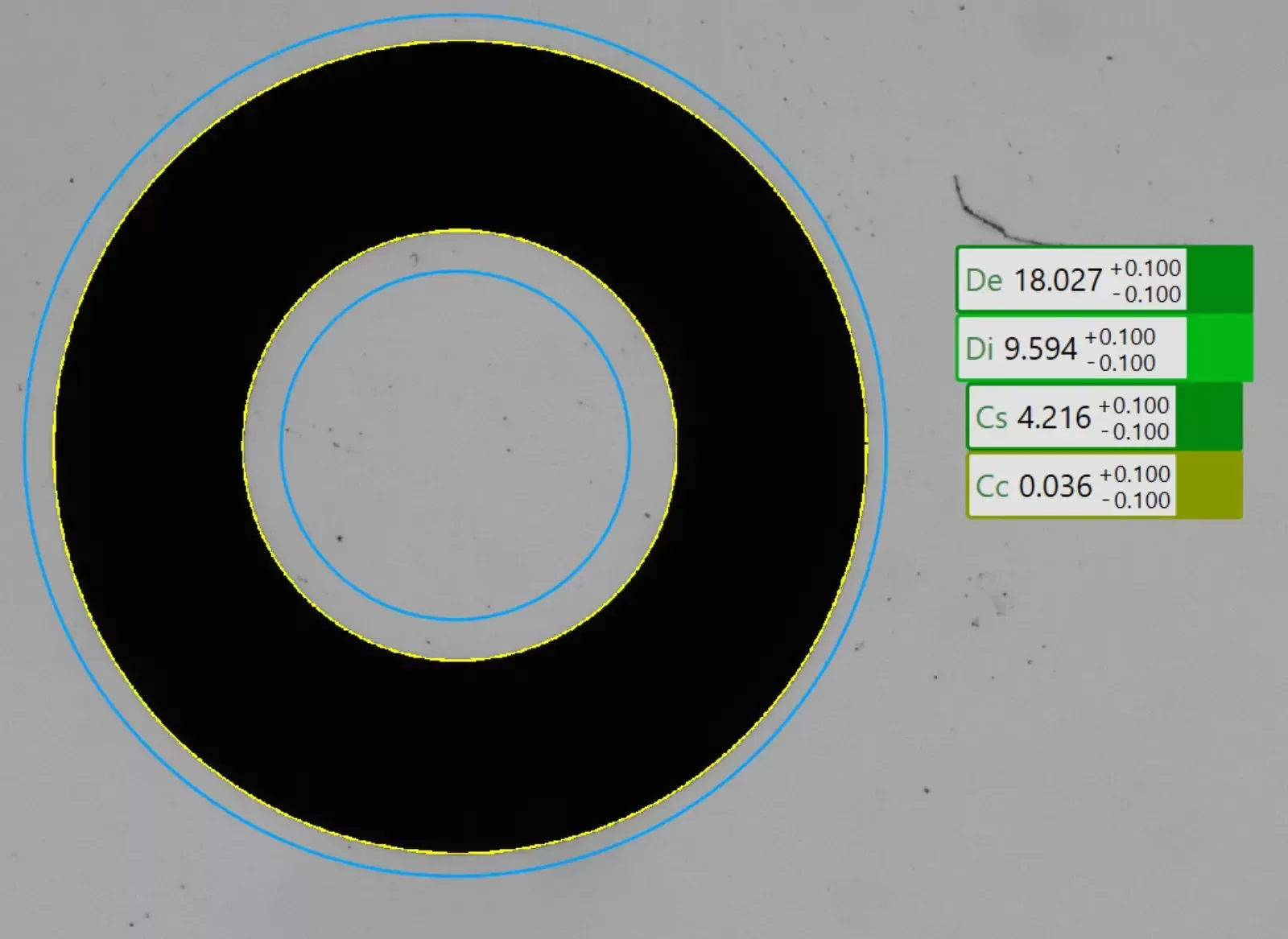
Advanced tool O-ring
The aim of this tool is to perform a dimensional analysis of O-Rings, reporting the relative dimensions of the external diameter, internal diameter, section and concentricity.
Photometry
The photometric analysis is executed by hitting the target with a light beam from different shooting angles in order to highlight the presence of riffles on the surfaces.
From this test, it is possible to obtain two types of data: the first one is the joint of the frames from different shooting angles and the second one shows the riffles through a graphical elaboration.
Depth from focus
With certain objects, there is a risk of losing focus in areas of the analyzed target. For example, if a strong zoom is used, this can cause areas closer or farther away to become out of focus. The Focus Stacking tool was created to solve this problem by taking and combining multiple images at different zoom levels (the number of images and the zoom level are determined by the user).
The result is a compound of the pictures.
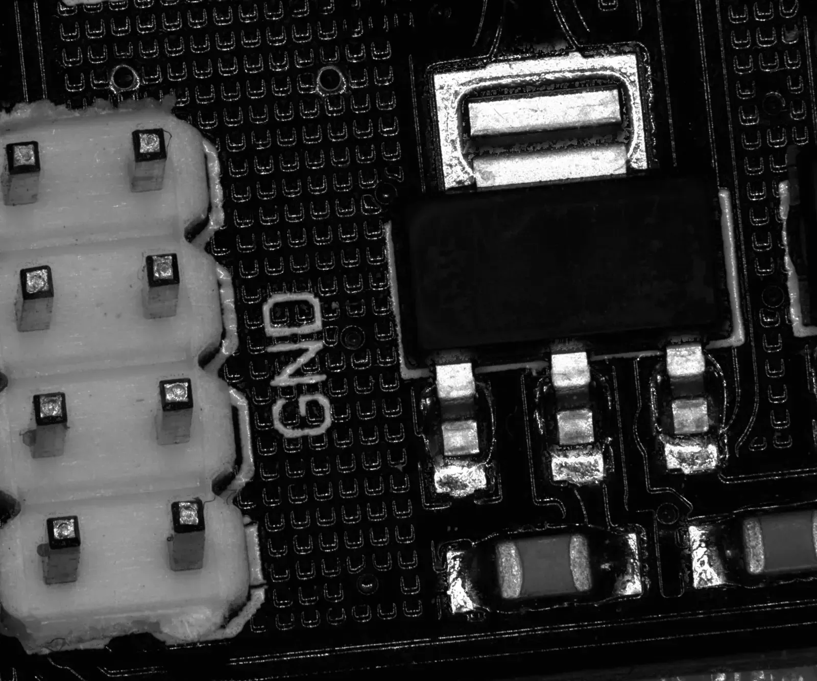
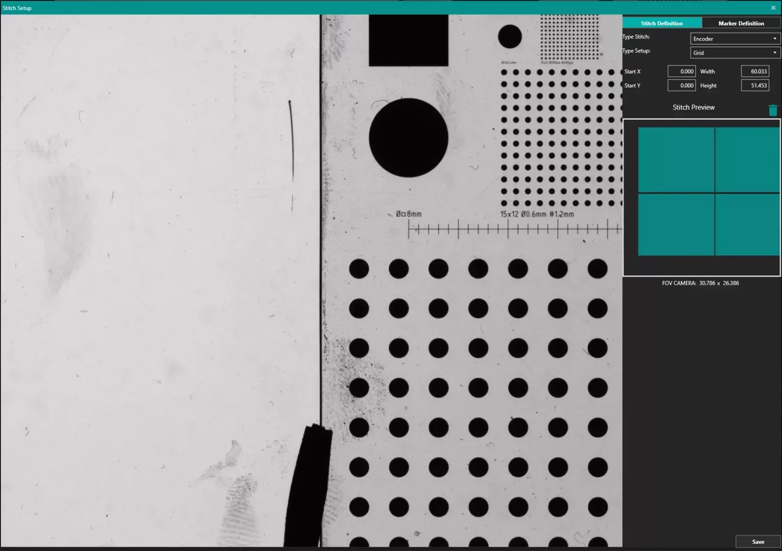
Stitch
The stitching tool allows to obtain an image that is a stitching of several images. This tool is created for machines with two degrees of freedom, by means of encoders parallel with the object plane.
One of the features is the possibility to choose the reference coordinates: either the encoder reference or, if these cannot be relied on, an optical reference, called marker which is selected by the user.
The acquisition could be manual or automatic, whilst the number of pictures taken is always decided by the user. Once the stitching is performed, the resulting image can be used in Horus as a normal input for a new program.
Horus Library
Horus library is an add-on through which the developer can integrate all the features of Horus inside their own software application. Horus library supports .NET, C#, VB programming languages and applications written in LabView.
