TC1MHR CORE series
Compact telecentric lenses for sensors up to 1/1.2”
Overview
Models
Downloads
Tech Info
Related
Resources

Magnification
0.087 - 0.222 x
Compact
Key advantages
- Excellent optical performances
TC1MHR CORE telecentric lenses deliver excellent optical performances as other comparable Opto Engineering® telecentric lenses. - Extremely compact
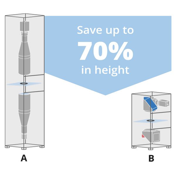
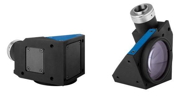
TC1MHR CORE lenses are up to 70% smaller than other telecentric lenses on the market. - Designed for flexibility and smart integration
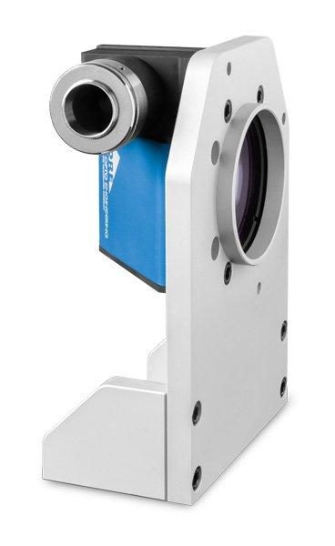
TC1MHR CORE lenses integrate a camera phase adjustment and can be mounted on multiple sides with or without clamps, allowing to cut costs. - Save you money
Systems integrating TC1MHR CORE lenses take much less space, resulting in lower manufacturing, shipping and storage costs. - Boost your sales
A smaller vision system or measurement machine is the solution preferred by the industry.
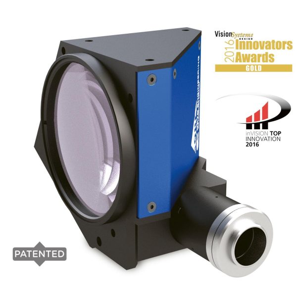
TC1MHR CORE series is a range of ultra-compact telecentric lenses tailored for high-resolution sensors up to 1/1.2”. TC1MHR CORE lenses deliver excellent optical performances in a super compact shape. Thanks to the unique opto-mechanical design, these lenses offer very high resolution, low F#, nearly zero distortion and high depth of field while saving up to 70% in length compared to similar FOV lenses on the market.
Thanks to the M6 threads located on multiple sides Opto Engineering® TC1MHR CORE lenses can be mounted in several orientations, even without clamping mechanics. For maximum flexibility, a special front mounting clamp is also available.
Discover more
ADVANTAGES
Cost reduction
- Lower manufacturing cost due to less material employed
- Less space required for storage and use
- Lower shipment expenses due to the smaller size
- Lower transportation risks
Sell more
- A smaller vision system or measurement machine is preferred by the industry


Please wait
Unable to process your request
Back to models
Filters
Close
Reset Filters
Notes
- Indicates the dimensions and shape of image, where "Ø =" stands for diameter and "x=" indicates the nominal image height and length (Tech Info for related drawing).
- Working distance: distance between the front end of the mechanics and the object. Set this distance within ± 3% of the nominal value for maximum resolution and minimum distortion.
- Working f-number (wf/N): the real f-number of a lens in operating conditions.
- Maximum angle between chief rays and optical axis on the object side. Typical (average production) values and maximum (guaranteed) values are listed.
- Percent deviation of the real image compared to an ideal, undistorted image. Typical (average production) values and maximum (guaranteed) values are listed.
- At the limits of the depth of field, the image can still be used for measurements. For a very sharp image, however, only half of the depth of field should be considered. Pixel size used for calculation is 3.45 μm.
- Object side, calculated with the Rayleigh criterion with λ= 520 nm
- Indicates the availability of an integrated camera phase adjustment feature.
- Due to the special shape of TCCR120xx it might be necessary to check the mechanical compatibility with your camera
Back to models
TC1MHR - TC4MHR CORE lens dimensions (A, B, C) and correct position of the sensor in relation to the lens
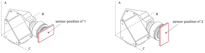
Sensor position

Image shape dimensions (Ø, x )
Video gallery

What is a TC and why is it useful?

How to pick the right telecentric lens

Common applications of TC lenses

Industry focus for Telecentric lenses