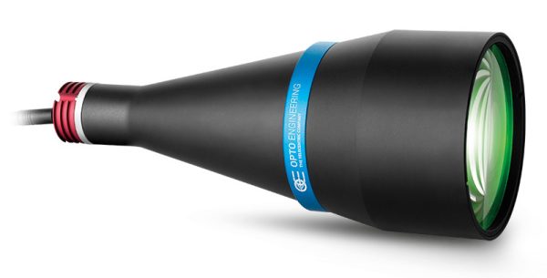
LTCLHP series
High-performance telecentric illuminators


Key advantages
- Complete light coupling
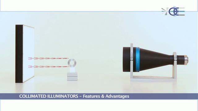
All the light emitted by a LTCLHP source is collected by a telecentric lens and transferred to the camera detector, ensuring very high signal-to-noise ratios. - Border effects removal
Diffused back-illuminators often make objects seem smaller than their actual size because of light reflections on the object sides, while collimated rays are typically much less reflected. - Improved depth of field and telecentricity
Collimated illumination geometry increases a telecentric lens' natural depth of field and telecentricity far beyond its nominal specs. - Homogeneity test report with measured values
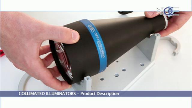
LTCLHP series are high-performance telecentric illuminators specifically designed to back illuminate objects imaged by telecentric lenses. This high performance series provides:
- Excellent illumination stability featuring no light flickering thanks to very high current stability over time even at low currents.
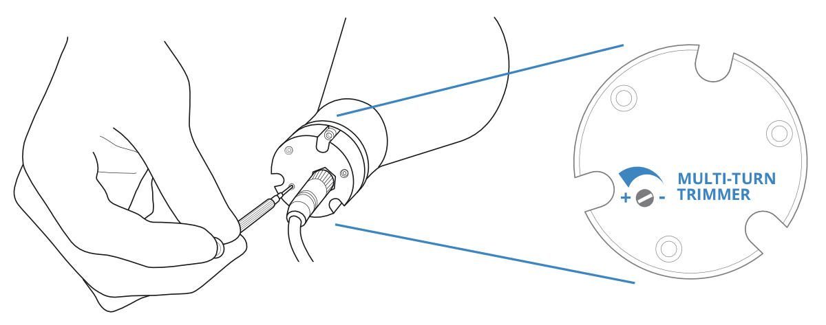
- Precise light intensity tuning thanks to the leadscrew multi-turn trimmer positioned in the back.
- Easy LED source replacement and alignment for all the LED colors offered by Opto Engineering®.
LTCLHP telecentric illuminators offer higher edge contrast when compared to diffused back light illuminators and therefore higher measurement accuracy. This type of illumination is especially recommended for high accuracy measurement of round or cylindrical parts where diffusive back lighting would offer poor performances because of the diffuse reflections coming from the edges of objects under inspection.
DID YOU KNOW?
LTCLHP series is now also available with new LTSCHP1W-GZ green light source, suitable for any kind of sample and specifically tailored for measuring reflective objects and objects with sharp edges.
KEY FEATURES
- Reduction of edge diffraction effects
- Enhanced illumination uniformity, especially on large FOVs
- Less sensitive to alignment
Ordering information
To order the version with the new green LED module use p/n LTCLHPxxx-GZ (i.e. LTCLHP064-GZ)
Real-world application examples and case histories
Notes
- Opto Engineering® recommends green light for high precision measurement applications
- Tolerance ± 10%
- At max forward current. Tolerance is ± 0.06V on forward voltage measurements
- In continuous mode (non-pulsed)
- At pulse width <= 10 ms and duty cycle <= 10%. Built-in electronics board must be bypassed (see tech info)
- Nominal value, with no spacers in place
Instructions for use
Operation options
LTSCHP LED modules can be operated in two ways:
- standard usage option: through the built-in electronics
- direct LED control usage option
STANDARD usage option (LED control through built-in electronics)
Only continuous mode (constant voltage) is allowed.
Connection:
Connect the black and the brown cables to your +12 / +24 V power supply.

Light intensity adjustment
The built-in multi-turn trimmer allows to control the light (LED forward current) intensity with a very high degree of precision: you can bring the current intensity from minimum to maximum with 21 full turns of the adjustment screw. Simply remove the protective cap and rotate counter-clockwise the adjustment screw to increase light intensity and vice versa.
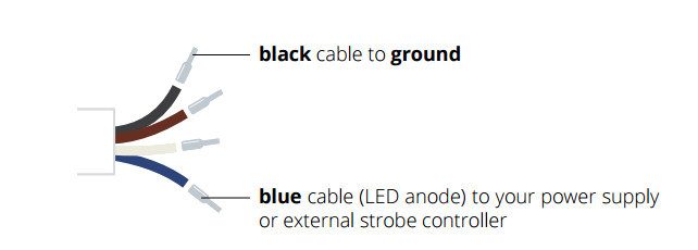
Direct LED control usage option
Both continuous and pulsed modes are allowed; the built-in electronics can be bypassed in order to drive the LED directly for use in continuous or pulsed mode. When bypassed, built-in electronics behave as an open circuit allowing direct control of the LED source. Please note that in such case light intensity adjustment is not possible through the built-in multi-turn trimmer.
Connection:
Connect the black and blue cables as shown below (remove the LED anode protective cover).
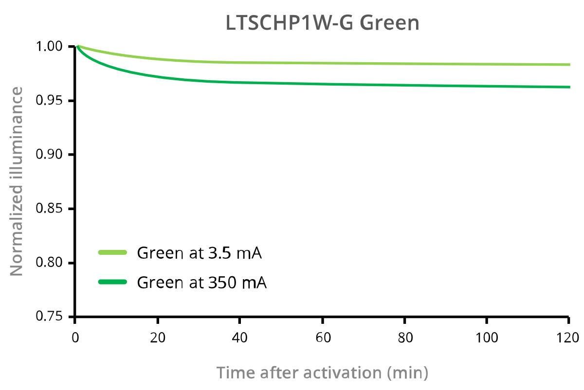
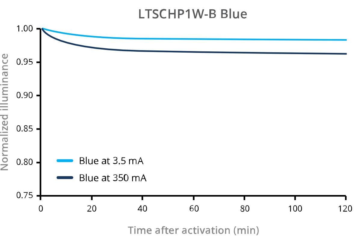
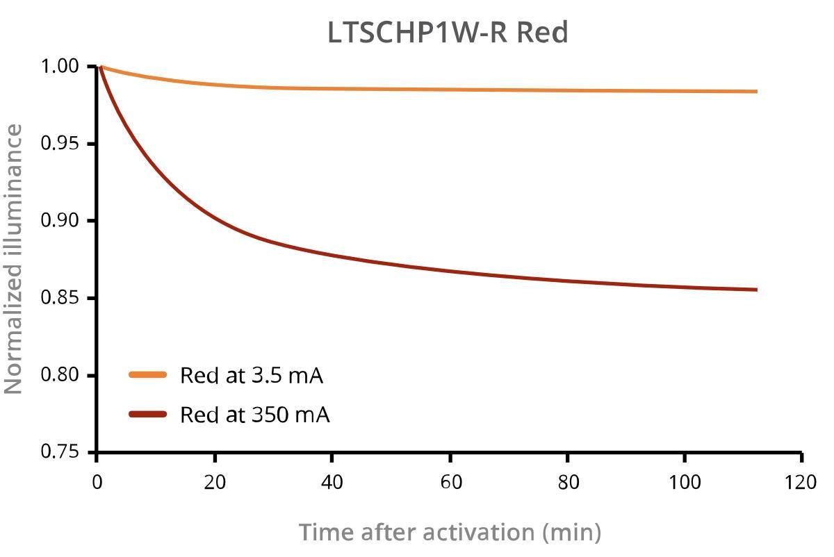
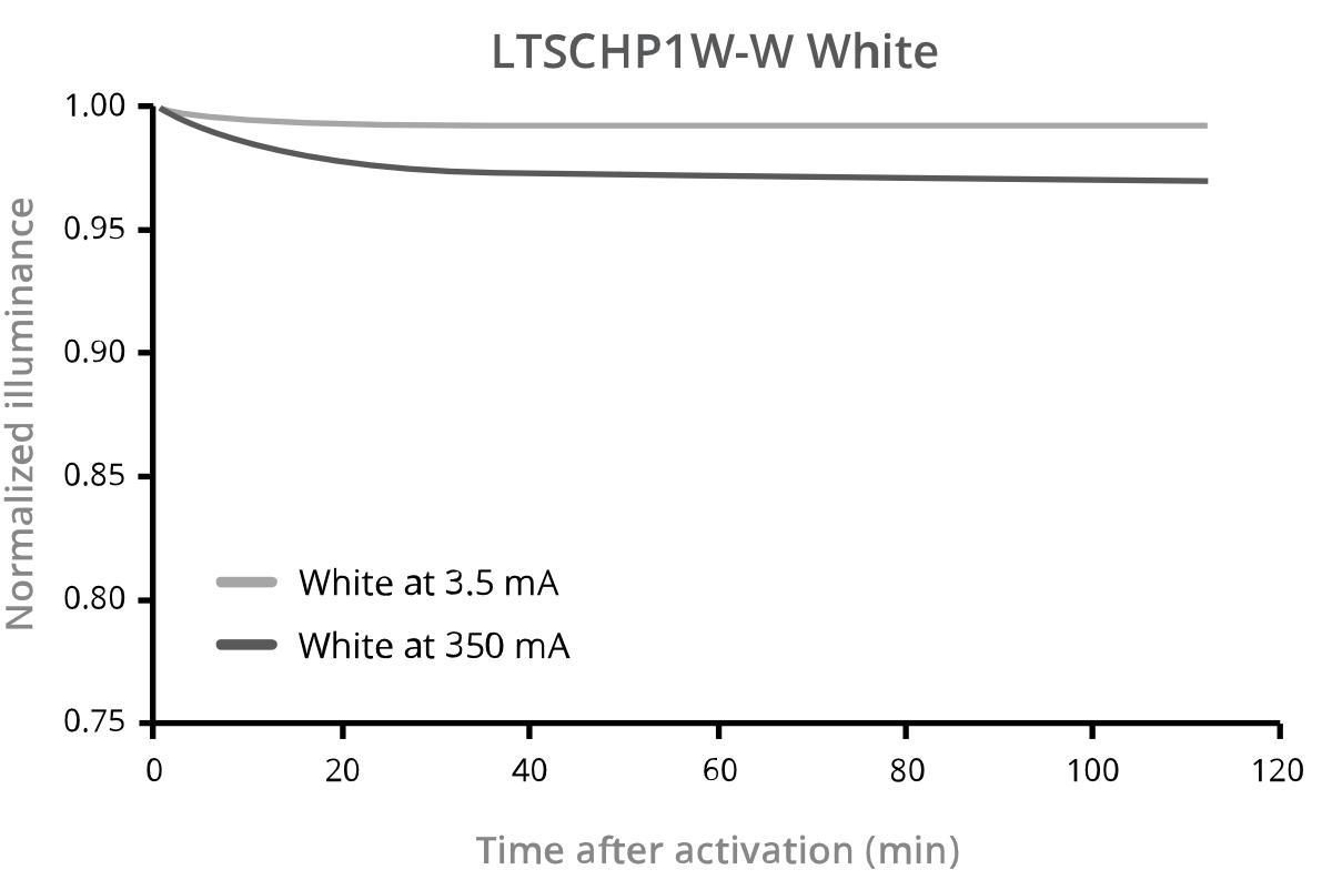
Illumination stability
In machine vision systems it is essential that flicker-free light appears to the camera in order to provide consistent and repeatable image output. LTCLHP collimated illuminators feature no light flickering thanks to very high current stability over time even at low currents 1 providing images with stable gray-level background 2. This is achieved through sophisticated built-in electronics which ensures constant current flow through the LED source and simultaneously lowers the noise level to the minimum. The state-of-the-art built-in electronics are the core of Opto Engineering® collimated illuminators built to provide excellent illumination stability, uniform light and low warm-up time (see graphs below).
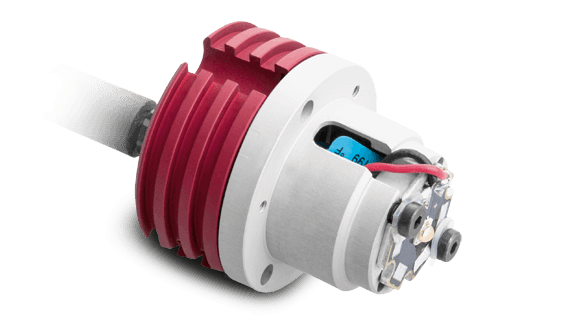
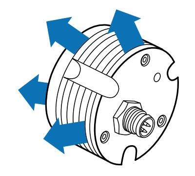
Easy LED replacement
All LEDs offered by Opto Engineering® can be easily replaced and positioned by the user using the provided LED centering tool which guarantees precise LED alignment. This way there is no need for soldering and no need to realign the imaging lens with LTCLHP collimated illuminator.
Wide selection of different colors
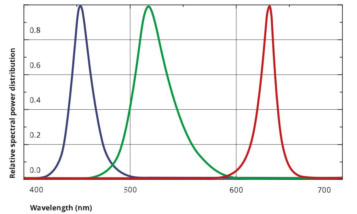
Available LED colors include:
R = red, peak at 630 nm
G = green, peak at 520 nm
B = blue, peak at 460 nm
W = white
Opto Engineering® recommends green light for high precision measurement applications: ensuring the lowest distortion and the highest telecentricity, also delivering the highest signal/noise ratio and the best image resolution.
Selecting the color of LTCLHP illuminators is easy: when ordering for example LTCLHP 064-G defines a LTCLHP 064 type collimated illuminator equipped with green (-G) LED.
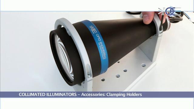
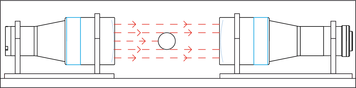
Easy and precise alignment with bi-telecentric lenses
Create the perfect optical bench for any precision measurement application by interfacing our bi-telecentric lenses and LTCLHP collimated illuminators using Opto Engineering® precision clamping mechanics CMHO series.
Each LTCLHP collimated illuminator up to LTCLHP 144-X can be mounted on the same clamping mechanics (CMHO series) used to fix and align our telecentric lenses.
Excellent thermal management
Stable illumination can only be achieved when heat dissipation is correctly managed. LTCLHP collimated illuminators provide stable illumination because they efficiently dissipate the heat generated by the built-in electronics and the LED source thanks to a suitable heat sink directly in contact with the inner circuitry. This way, a low LED junction temperature in maintained ensuring optimal optical output performances (see graphs below)
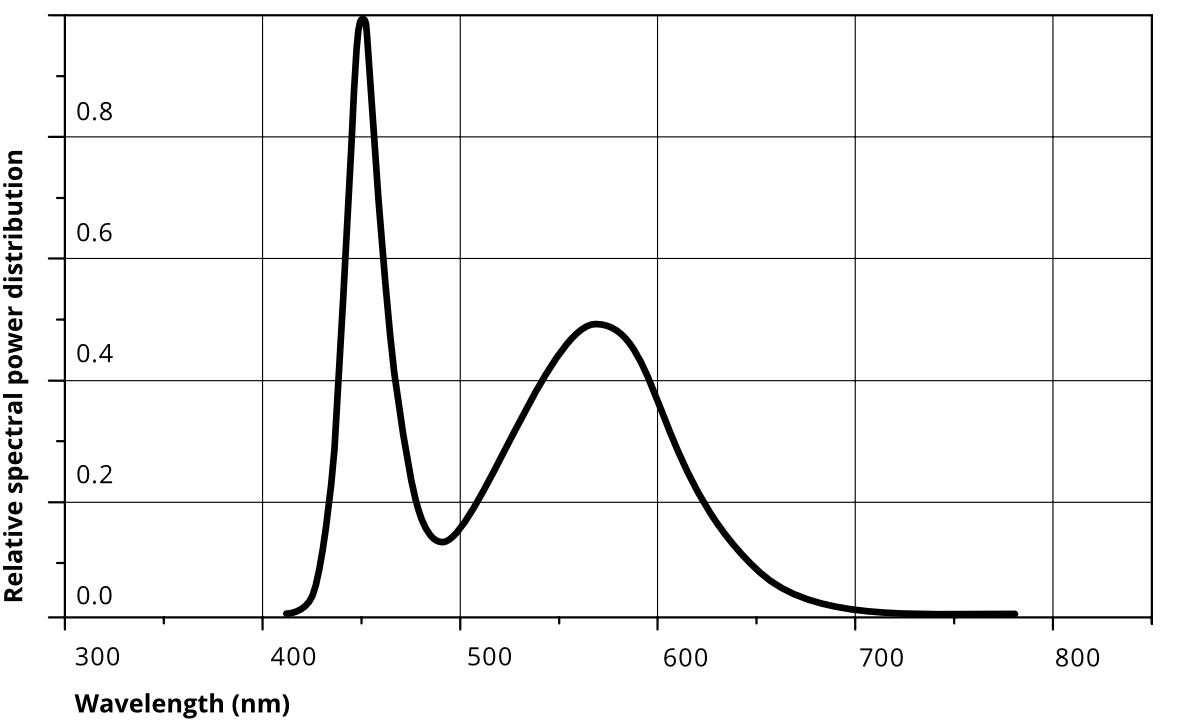
Warm-up times
Typical warm-up times at minimum and maximum LED forward current.
Normalized Illuminance graphs indicate typical warm-up times for green, blue, red and white light sources.
About LED source axial position
LED axial position is an important operational parameter that must be correctly set to obtain optimal illumination homogeneity. LED axial position is adjusted at factory by placing/removing internal or external spacers of various thicknesses.
Each LTCLHPxxx illuminator is configured by default with the number and type of spacers needed to achieve the best illumination homogeneity with its corresponding TC23xxx telecentric lens model. The number and type of spacers needed to achieve optimal light homogeneity can be different when LTCLHPxxx is used in combination with TC13xxx, TC12xxx or telecentric lenses designed for other sensor sizes.
NOTES
- Less than 1‰ variation in LED forward current intensity.
- Variation of mean gray level between 10 consecutive images
- 21 full turns are required to bring the light intensity from minimum to maximum.
- Make sure that the maximum rates are not exceeded to avoid electrical shorts.
Video gallery