TC12K series
Telecentric lenses for sensors up to 62 mm and 12k line scan cameras
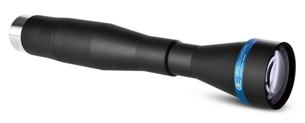


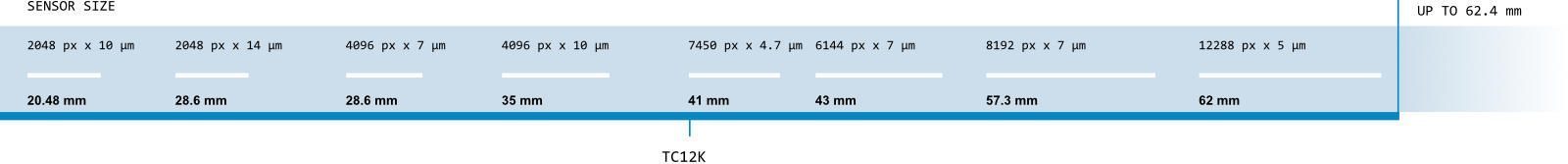
TC12K series telecentric lenses are designed to fit very large line detector cameras. An image circle diameter larger than 62 mm combined with very high resolution makes the TC12K series ideal for 12k and 16k resolution cameras.
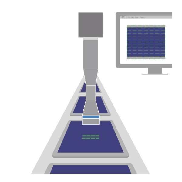
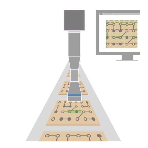
Flat panel display, solar cell and electronic board inspection are among the most common applications of these optics in the electronics industry; at the same time the optical specifications make them perfectly suitable to accurately measure large mechanical parts. In addition to the standard M72x0.75 mount, TC12K lenses can be equipped with other camera mounts ensuring wide compatibility with most common line scan cameras.
Application examples

Which telecentric lens is right for my application?
It depends on your detector resolution and the size of the sample to be inspected: our imaging lens selector will guide you through all the possible sample/lens/detector combinations.
Notes
- Working distance: distance between the front end of the mechanics and the object. Set this distance within ±3% of the nominal value for maximum resolution and minimum distortion.
- Working f-number (wf/N): the real f-number of a lens in operating conditions.
- Maximum angle between chief rays and optical axis on the object side. Typical (average production) values and maximum (guaranteed) values are listed.
- Percent deviation of the real image compared to an ideal, undistorted image. Typical (average production) values and maximum (guaranteed) values are listed.
- At the limits of the depth of field, the image can still be used for measurements. For a very sharp image, however, only half of the depth of field should be considered. Pixel size used for calculation is 7 μm.
- Object side, calculated with the Rayleigh criterion with λ= 520 nm
- FD stands for Flange Distance (in mm), defined as the distance from the mounting flange (the “metal ring” in rear part of the lens) to the camera detector plane.
- Indicates the availability of an integrated camera phase adjustment feature.
- Measured from the front end of the mechanics to the camera flange.
Wide image circle
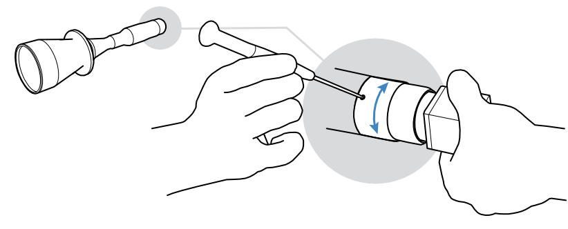
Phase adjustment
Adjusting the phase of the camera mounted on TC12K telecentric lenses is easy: simply loosen the three set screws and rotate the camera mount until you achieve the desired angular alignment.
Video gallery


