LTSCHP series
High-performance replacement LED modules

LTSCHP modules power several Opto Engineering® LED illuminators and feature excellent current stability.
They are available in various colors and can be ordered as spare parts:
1W power sources:
• LTSCHP1W modules are compatible with LTCLHP, LTLCHP CORE (only red, green and white), LTCL4K, TCCXQ, TCCX, TCBENCH series, TCBENCH CORE, MZMT12X series and TCKIT case.
• The new LTSCCP1W-G green light source is compatible with the LTLHP CORE PLUS series.
• The new LTSCHP1W-GZ green light source is now also available: suitable for any kind of sample, it is specifically tailored for measuring reflective objects and objects with sharp edges. In fact, it reduces edge diffraction effects, also ensuring superior illumination uniformity (especially on large FOVs) and making the whole system less sensitive to alignment. It is compatible with LTCLHP, TCBENCH, LTCL4K, LTCLHP CORE, TCBENCH CORE series and TCKIT case.
3W power sources:
• LTSCHP3W modules are compatible with LTPRHP3W and LTPRSMHP3W pattern projectors.
Notes
- Tolerance ± 10%
- At max forward current. Tolerance is ± 0.06V on forward voltage measurements
- In continuous mode (non-pulsed)
- At pulse width <= 10 ms and duty cycle <= 10%. Built-in electronics board must be bypassed (see tech info)
Instructions for use
Operation options
LTSCHP LED modules can be operated in two ways:
- standard usage option: through the built-in electronics
- direct LED control usage option
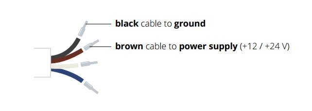
STANDARD usage option (LED control through built-in electronics)
Only continuous mode (constant voltage) is allowed.
Connection:
Connect the black and brown cables to your +12 / +24 V power supply.
Light intensity adjustment
The built-in multi-turn trimmer allows to control the light (LED forward current) intensity with a very high degree of precision: you can bring the current intensity from minimum to maximum with 21 full turns of the adjustment screw. Simply remove the protective cap and rotate counter-clockwise the adjustment screw to increase light intensity and vice versa.

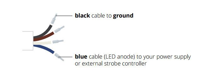
Direct LED control usage option
Both continuous and pulsed mode are allowed; the built-in electronics can be bypassed in order to drive the LED directly for use in continuous or pulsed mode. When bypassed, builtin electronics behaves as an open circuit allowing direct control of the LED source. Please note that in such case light intensity adjustment is not possible though the built-in multi-turn trimmer.
Connection:
Connect the black and blue cables as shown below (remove the LED anode protective cover).
Make sure not to exceed LEDs maximum rates to avoid electrical shorts.