PC series
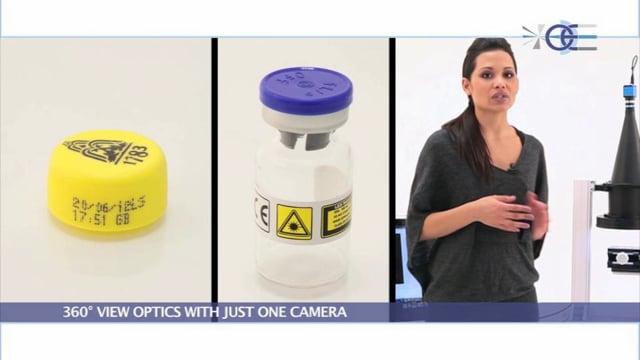
Pericentric lenses for 360° top and lateral view with just one camera
Product range expansion – Discover all the brand-new pericentric lenses now available:

Key advantages
- Just one camera
No need for multiple cameras placed around and over the object. - Fast image analysis
No image matching software is needed as the picture is not segmented. - Single point of view
No perspective effects typical of multi-image systems. - Smooth online integration
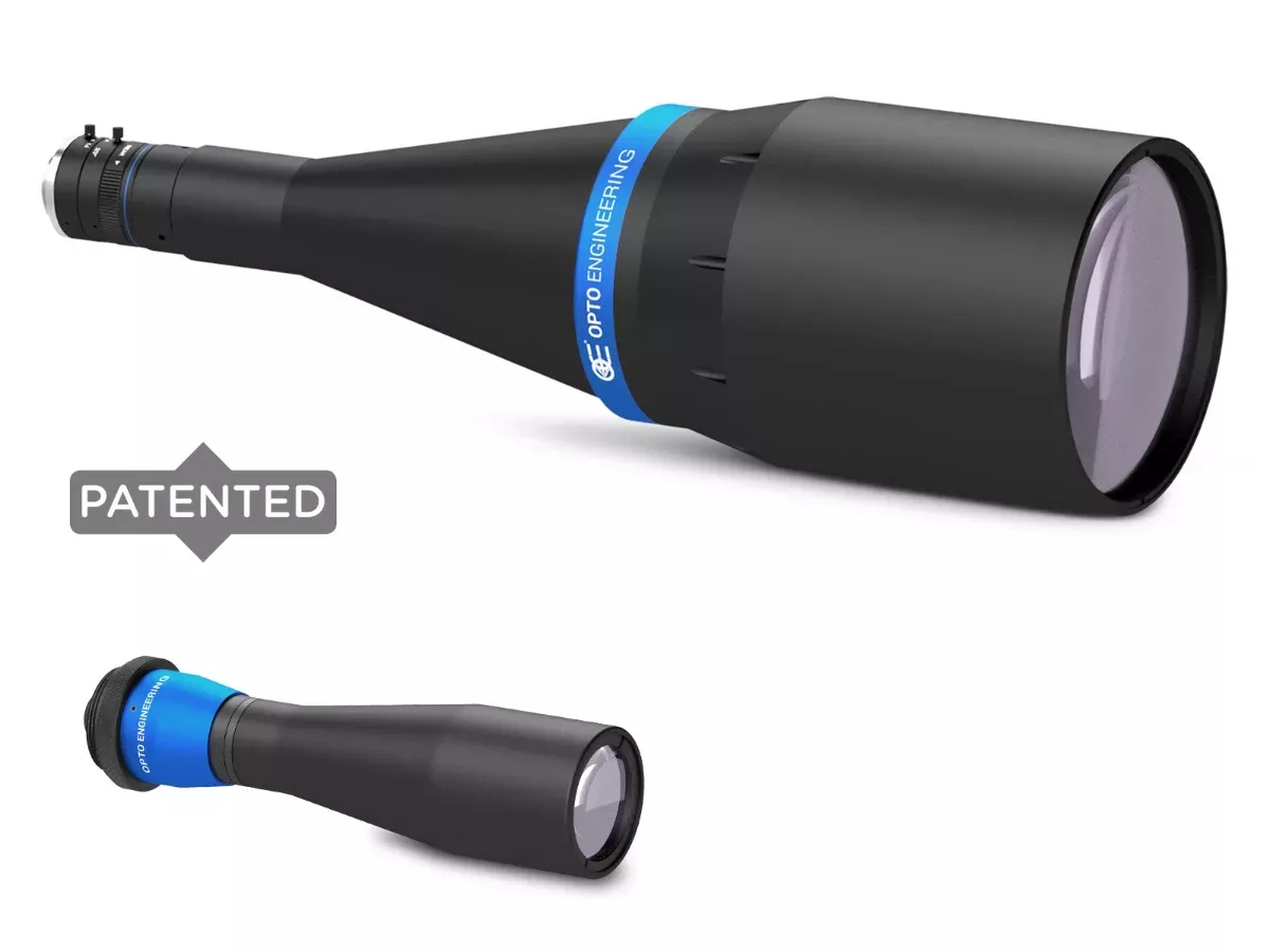
Inspected parts pass unobstructed in the free space below the lens. - Nano model available for the inspection of small objects, from 2 to 12 mm in diameter
- Industrial design and compact solutions
for applications with reduced space
PC pericentric lenses are unique 360° view lenses designed to perform all-round inspection of objects from 2 mm up to 65 mm in diameter, quickly and reliably.
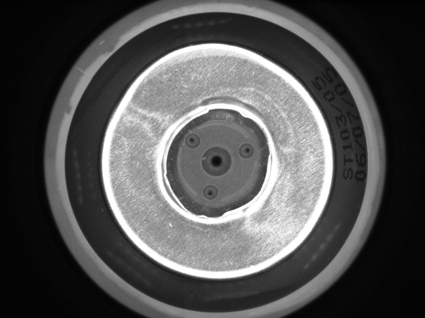
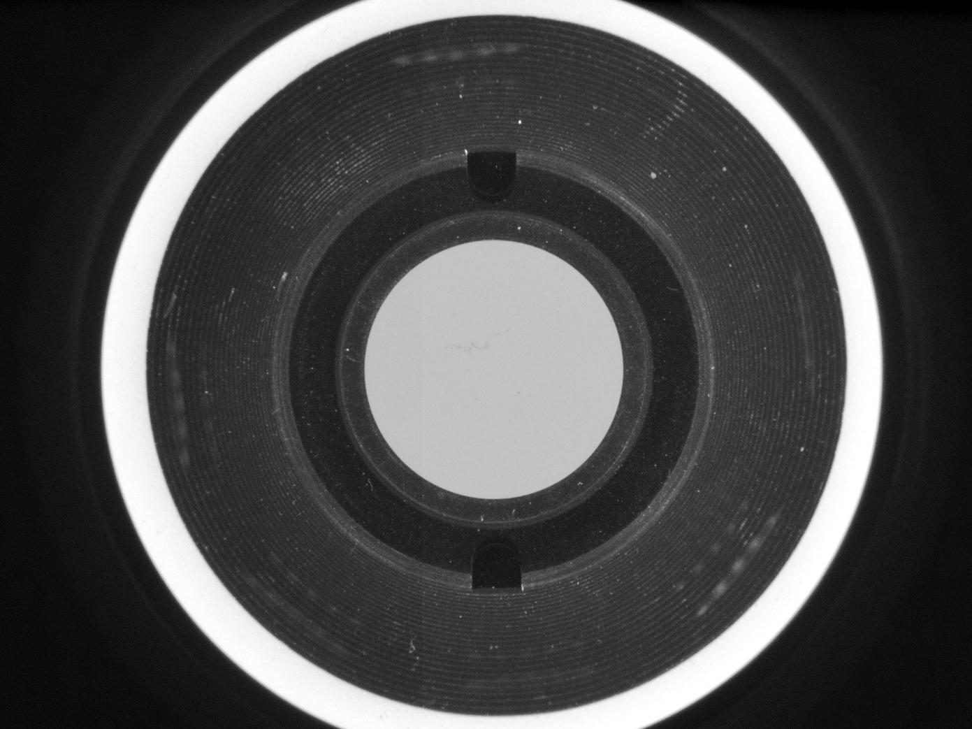
The innovative design allows one camera to see the top and lateral surfaces of an object in perfect focus all in one image. This allows you to greatly simplify the layout of the vision system, with no need for multiple cameras, lenses or mirrors.
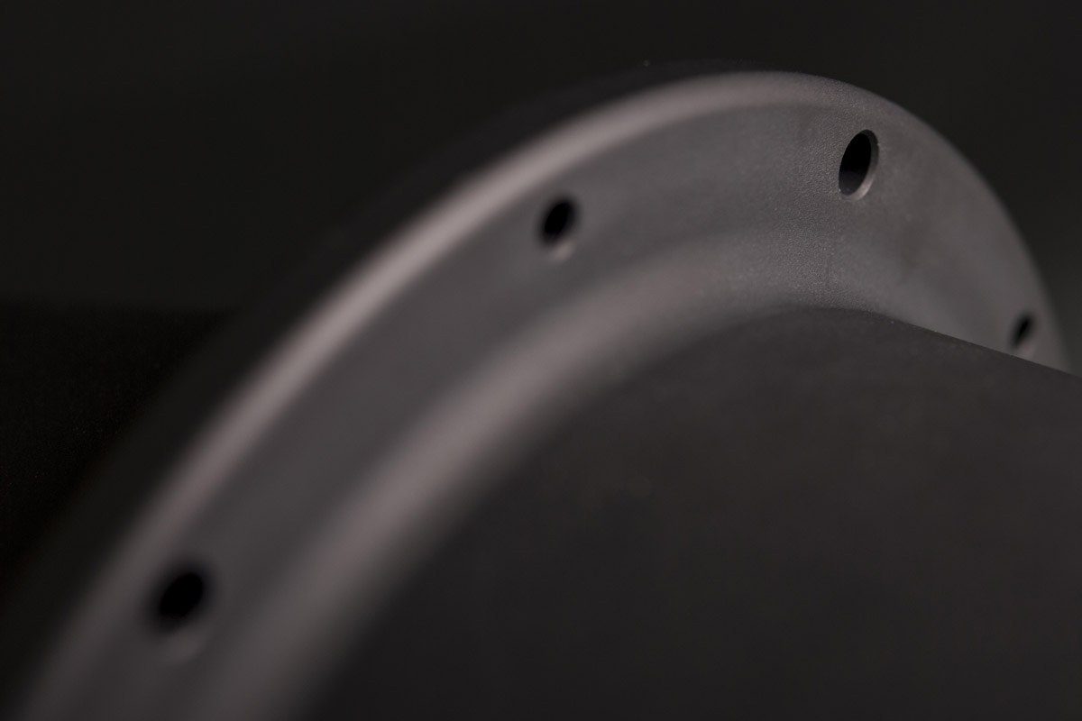
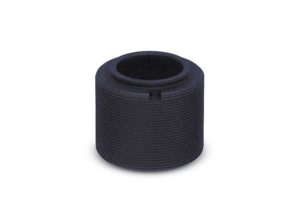
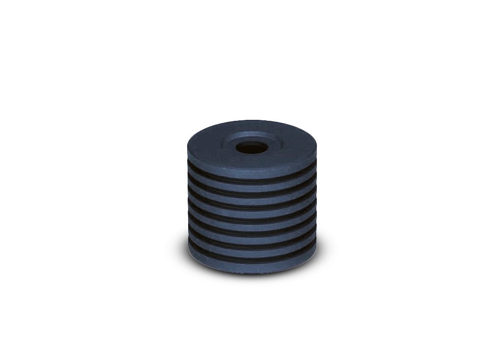
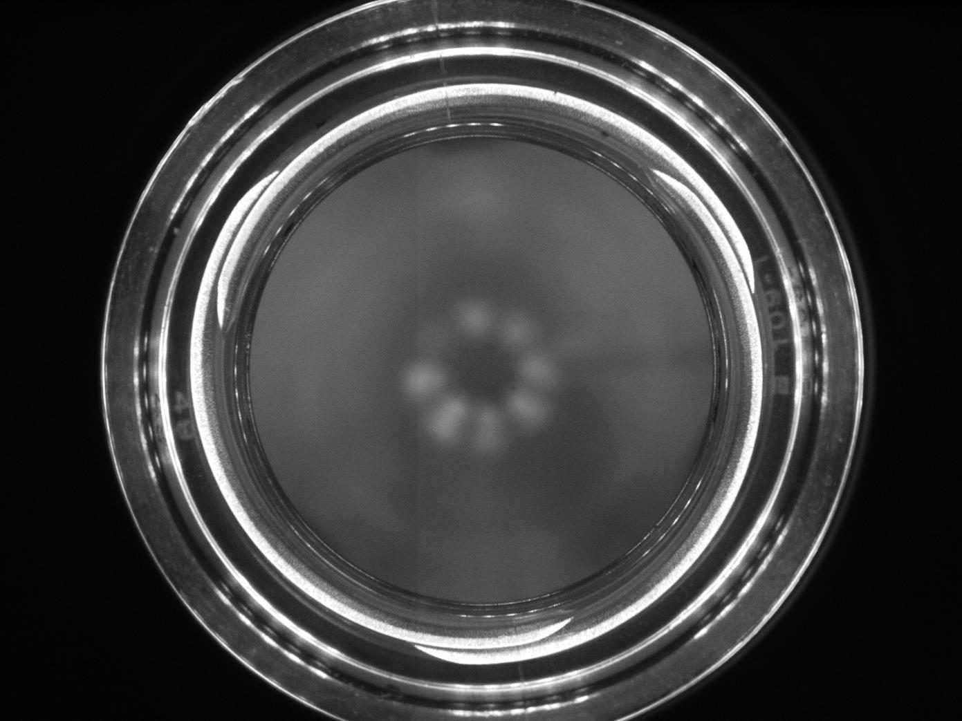
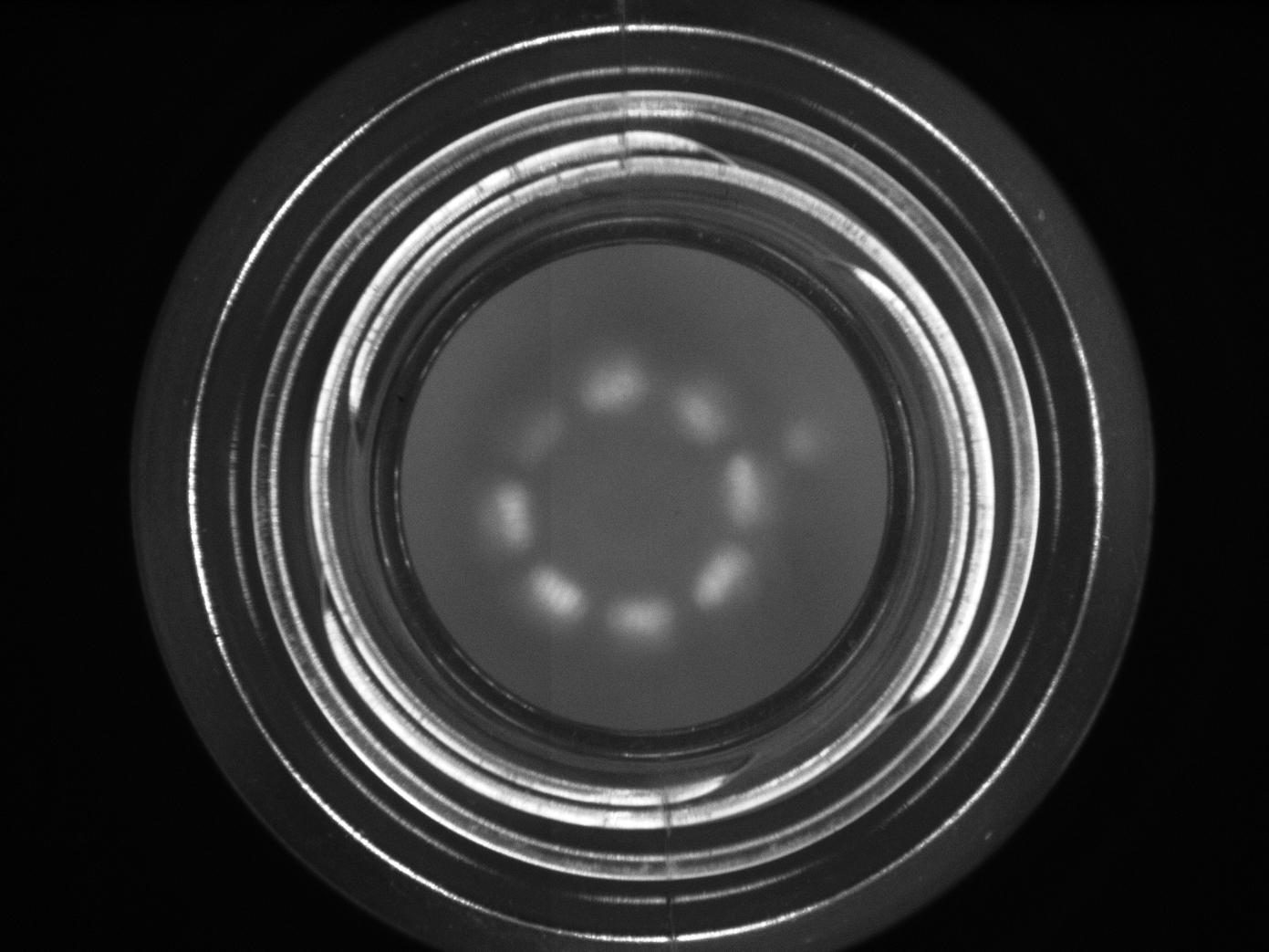
The term pericentric comes from the specific path of the light rays: the lateral surface of the object appears to be wrapped around the top face, making the PC series ideal for cylindrical objects which are very common in the beverage, pharmaceutical, automotive and metal industry.
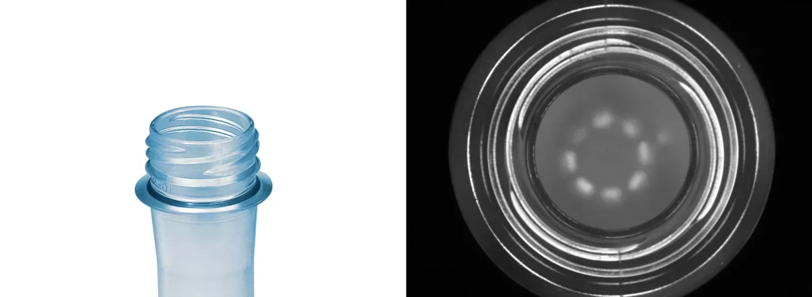
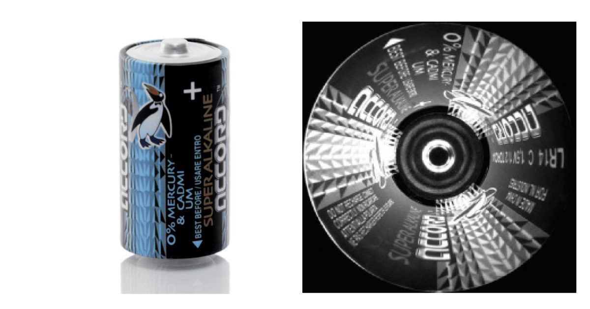
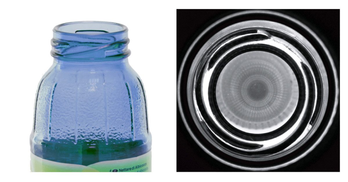
Typical applications include bottleneck thread inspection and data matrix reading - the code will always be properly imaged regardless of its position.
Working principle
PC optics are designed to work with 1/3”, 1/2” and 2/3” detectors. These detectors ensure the most appropriate optical magnification factor to achieve the depth of field required by high-resolution 3D pericentric imaging.
The image of the top of the object and its sides are inscribed into the short side of the camera detector.
The smaller the object diameter, the larger the object height which can be inspected, while short objects can be inspected over a larger diameter.
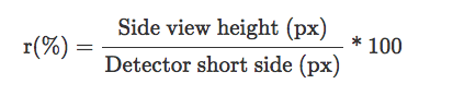
The tables below show possible combinations of object diameters and heights along with the appropriate working distance and recommended F-number; the “r” parameter for each configuration is also listed.
The “r” parameter is the ratio between the side view height (the circular crown thickness) and the detector short side. It provides information about side view resolution. The higher the “r” value, the higher the resolution that can be achieved in the side view.


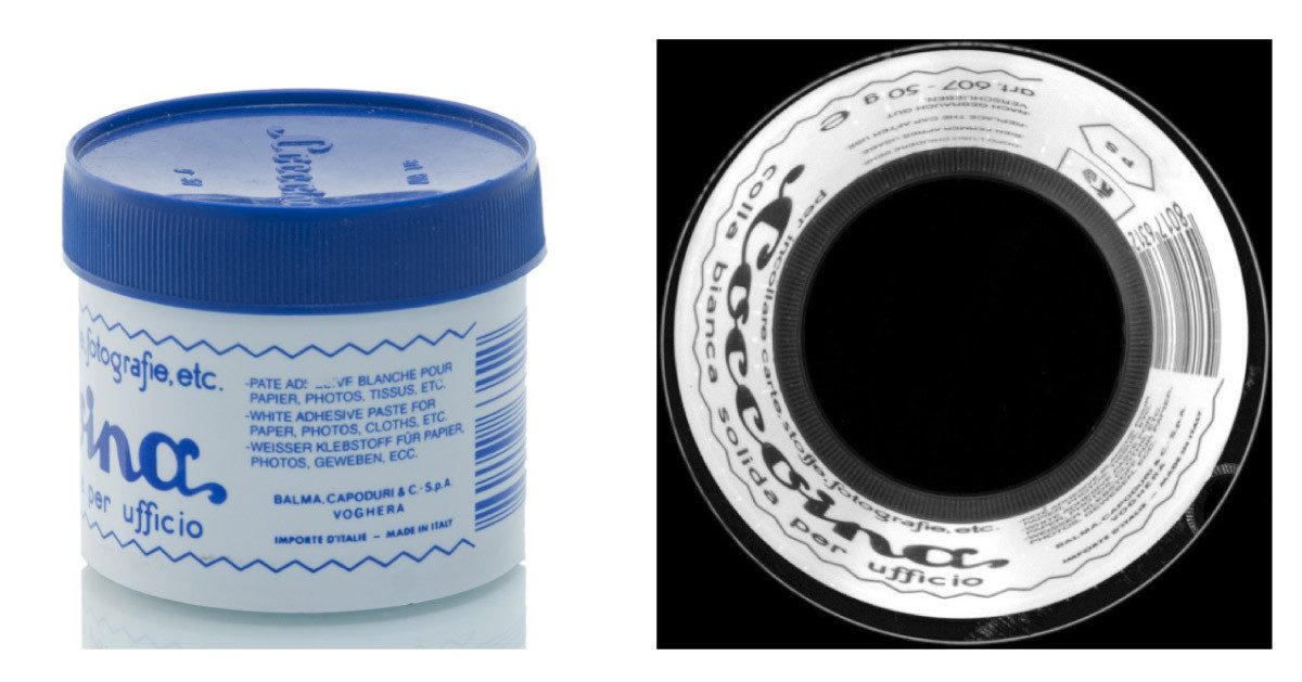
Application examples
Notes
- For the complete information about the inspectable field of view, see the datasheet of the objective
- The maximum inspectable field of view is given considering zero working distance. While keeping the diameter constant, a working distance greater than zero will decrease the height of the inspectable object accordingly.
- Working distance: distance between the front end of the mechanics and the object.
- The f-number could be changed using the variable iris.
- Measured from the front end of the mechanics to the camera flange.
Technical documents
Video gallery

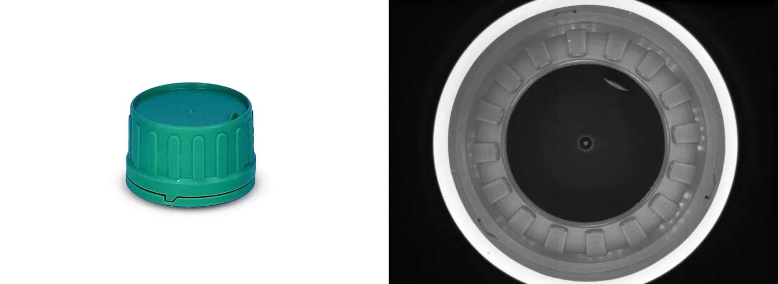
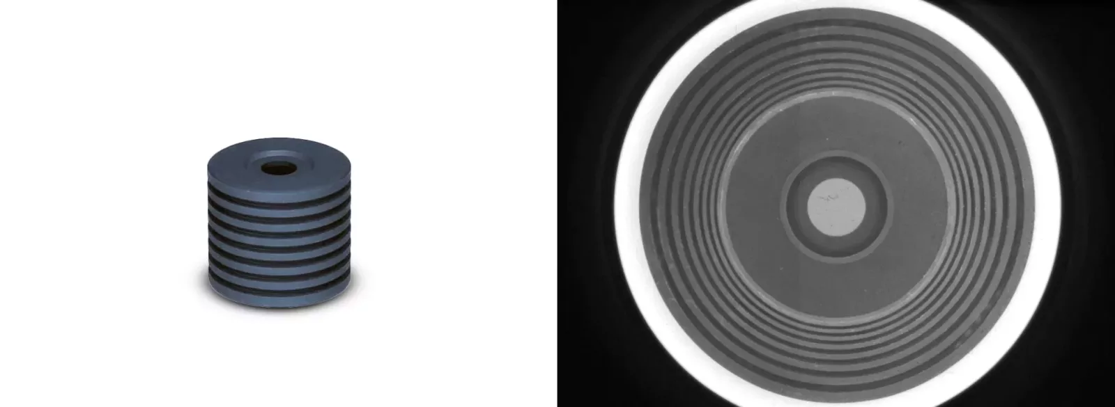
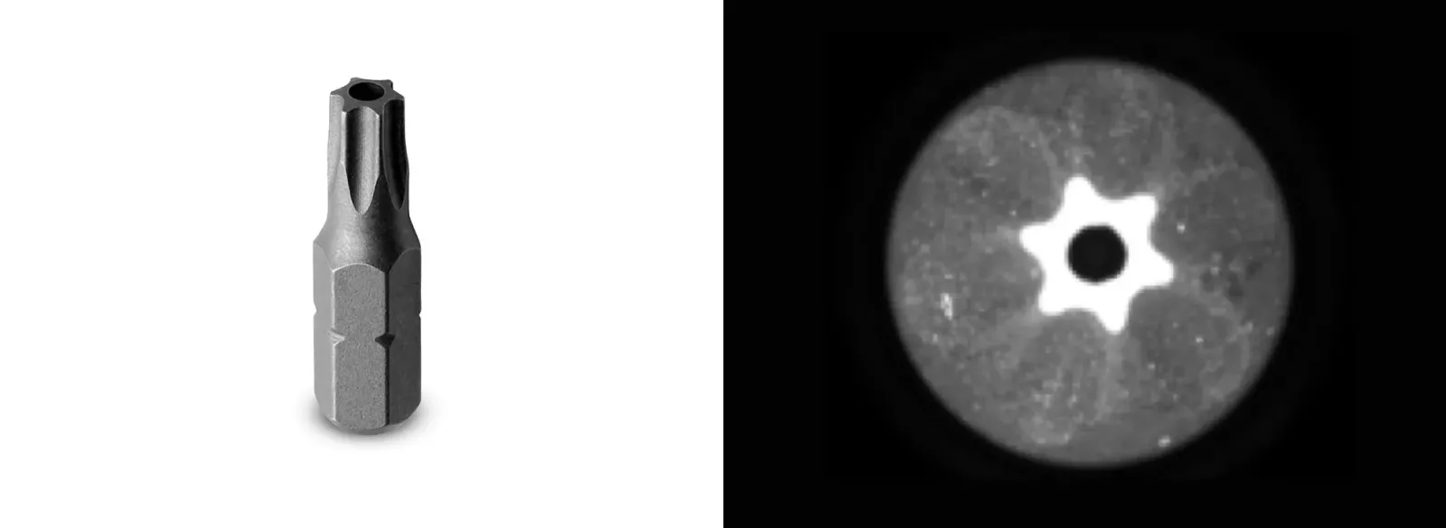
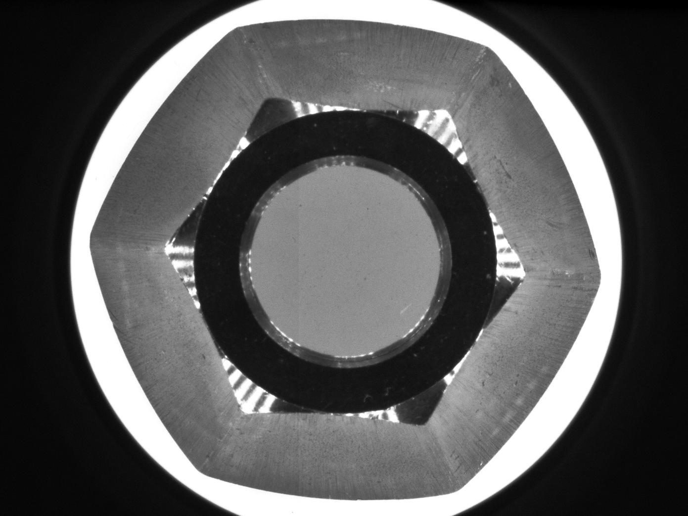
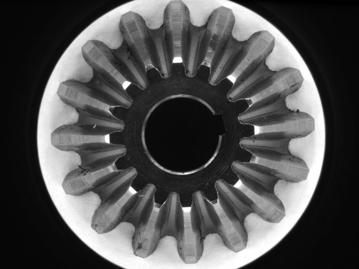
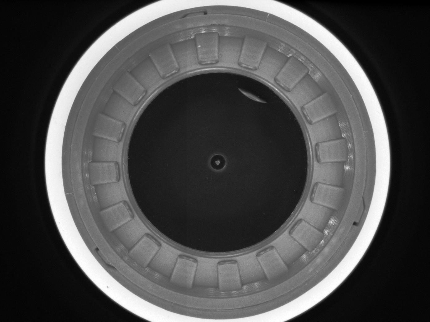
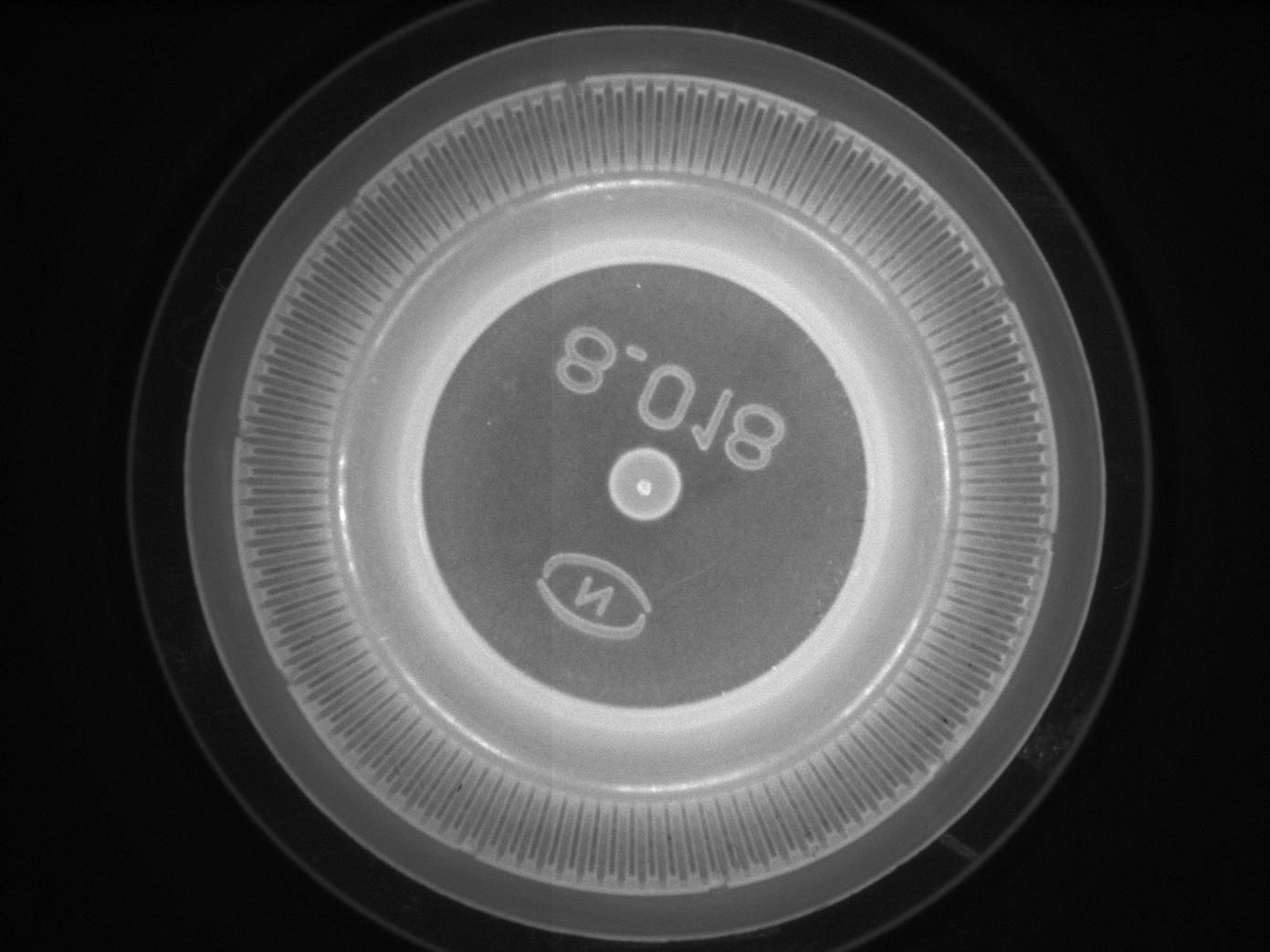
Examples of pericentric images
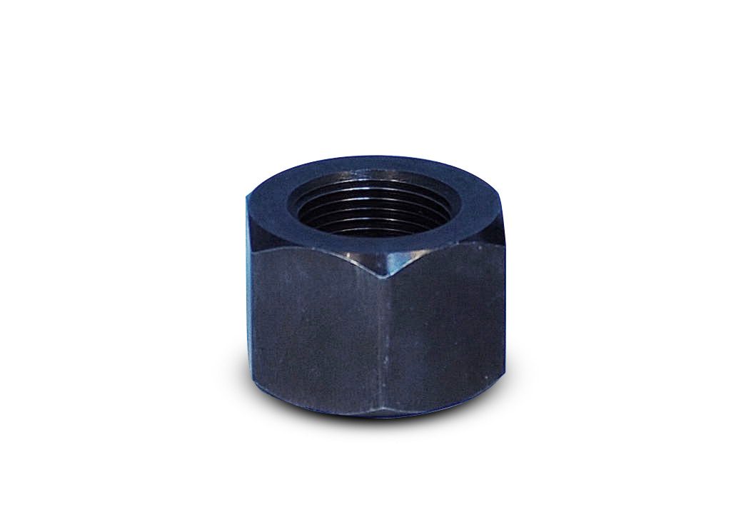
Large nut
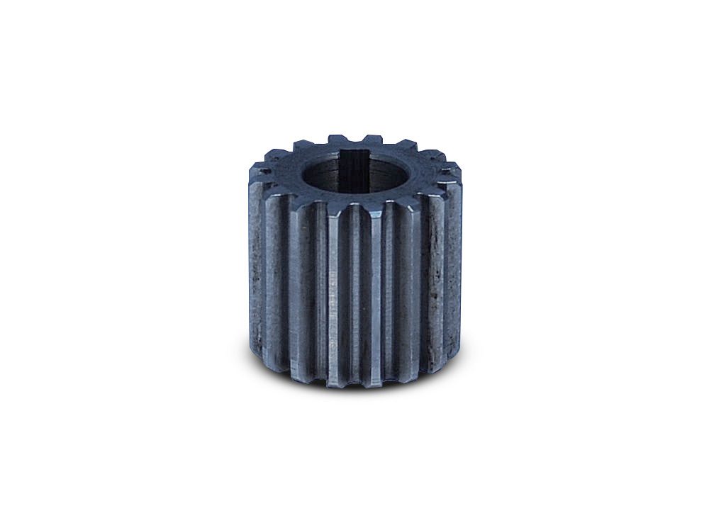
Sprocket
Tight threading nut
Mechanical part

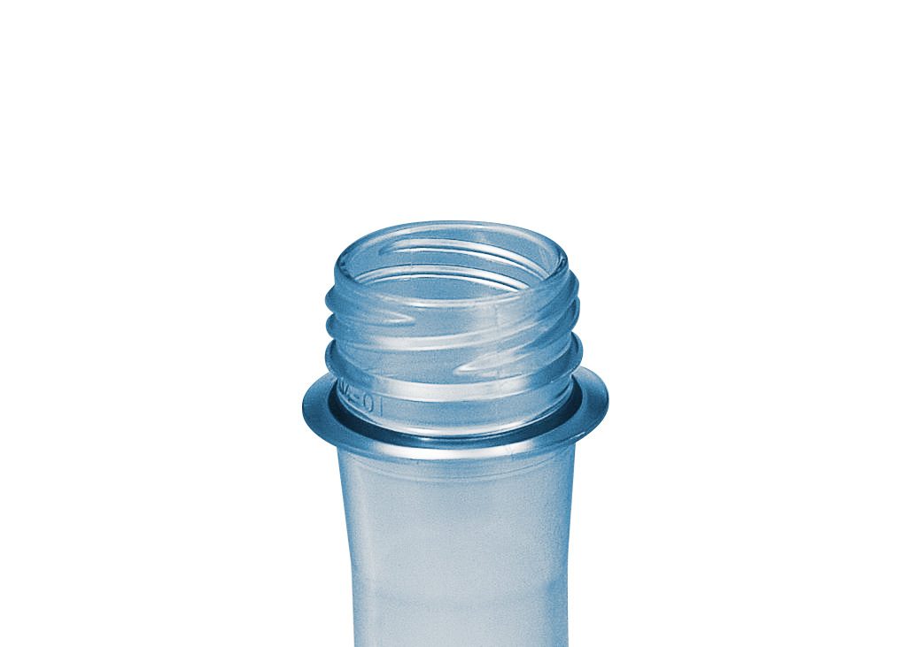
Large preform
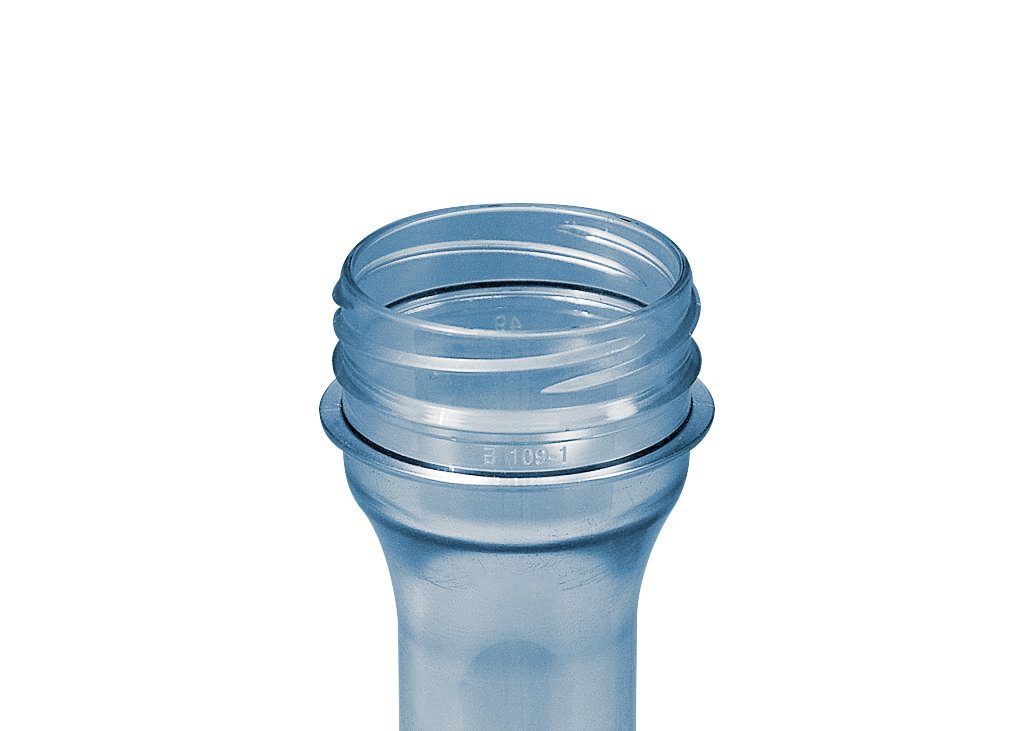
Small preform
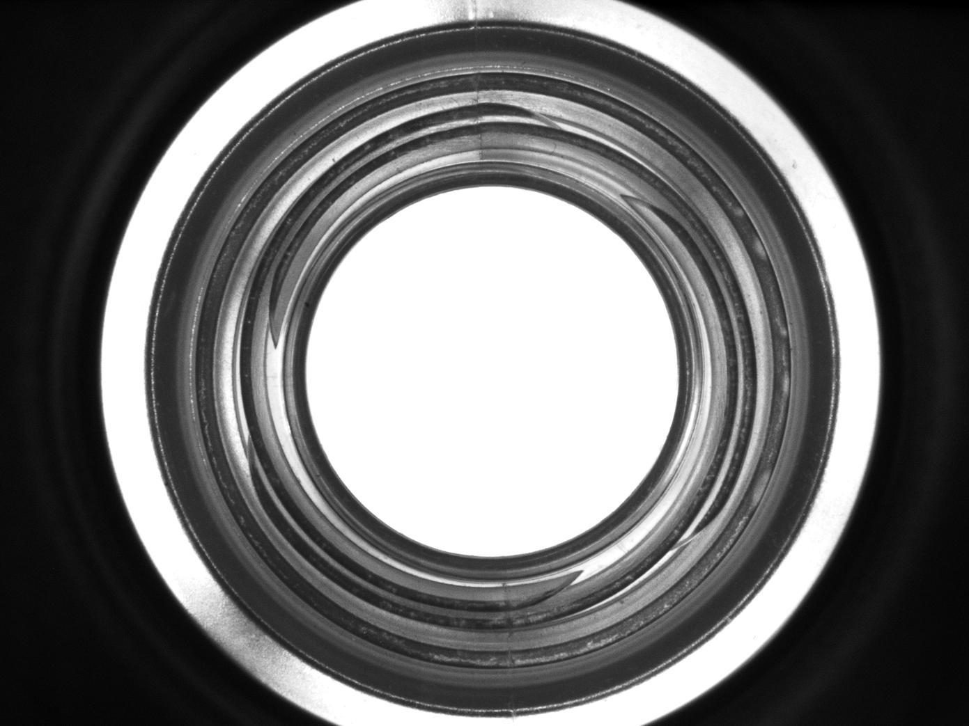
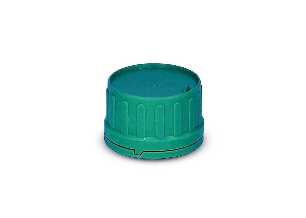
Large cap
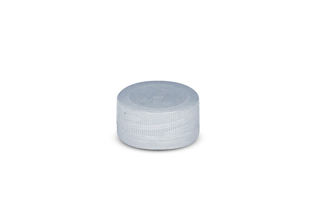
Small cap
Plastic container

Flask cap