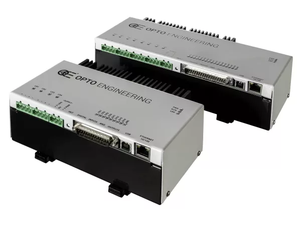
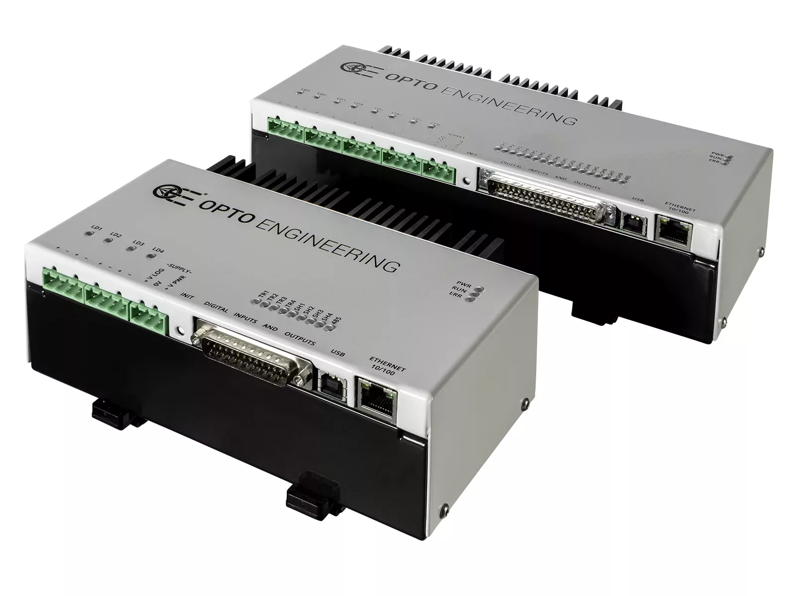
LTDV series
LED lighting strobe controllers
Product Change Notification: Starting from March 1, 2026, the models LTDVE1CH-40F, LTDVE2CH-20F, LTDVE4CH-20, and LTDVE8CH-20 will be supplied with new firmware. Existing units of LTDVE1CH-40F, LTDVE2CH-20F, and LTDVE4CH-20 can be upgraded to the new version. For further information, please refer to the related Product Change Notification.
Key advantages
- Industrial design with opto-isolated I/O signals
- High precision LED strobe control with configurable timing
- Wide interface compatibility for integration into PC and PLC systems*
- Up to 8 independently controlled output channels
- High output currents with options for intensive LED loads
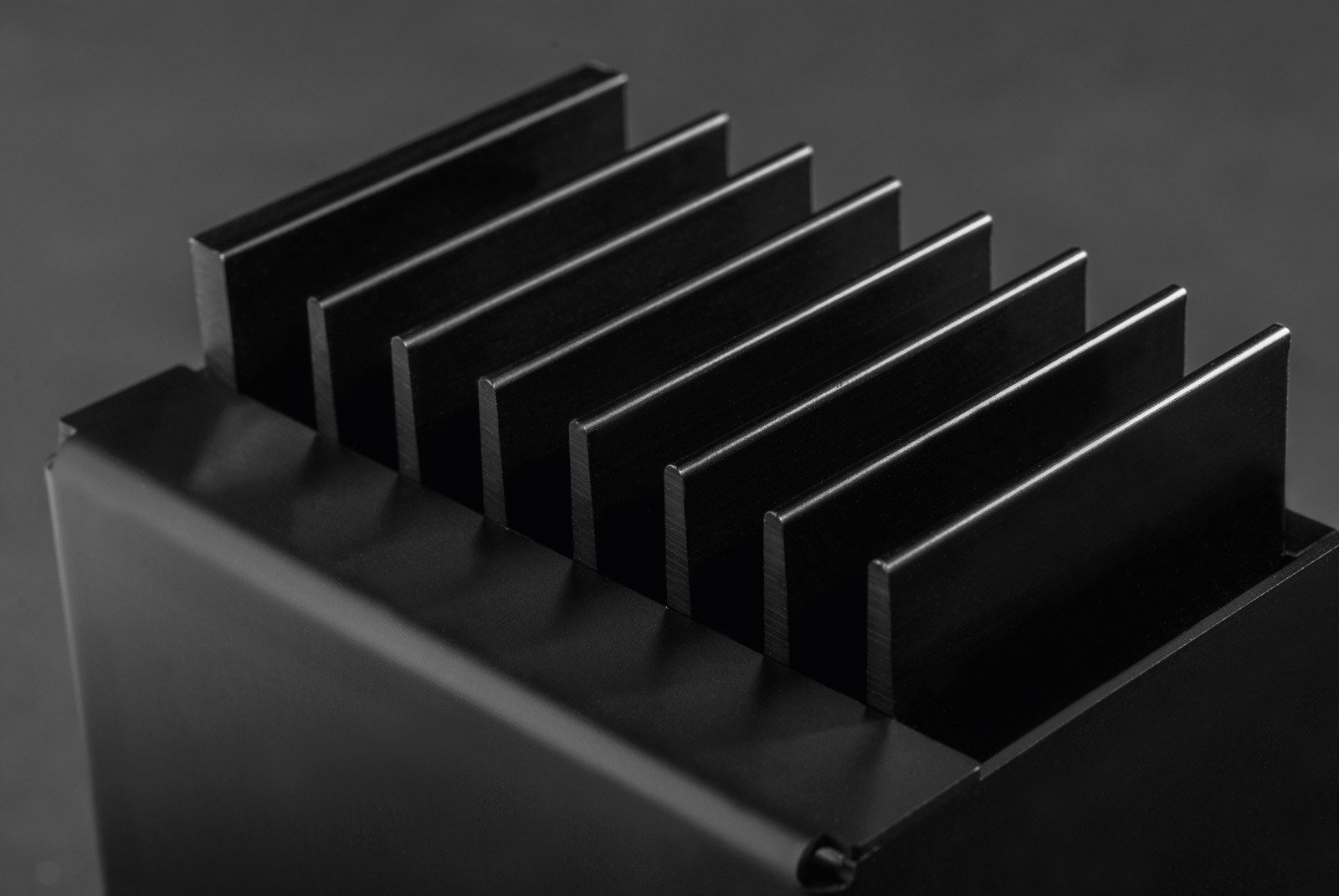
- Integrated thermal overload protection*
* available on selected models
Opto Engineering® LTDV Series LED strobe controllers deliver precise, high-speed and fully synchronized light control for demanding machine vision applications.
Designed to ensure repeatable and accurate strobing, LTDV controllers allow independent adjustment of current intensity, pulse duration and delay. Advanced trigger filtering guarantees stable and noise-immune operation, while precise synchronization with camera exposure ensures reliable performance even in high-speed inline inspection systems.
The LTDVE models feature Ethernet and RS485 interfaces with Modbus RTU and Modbus TCP protocols, enabling seamless integration with PLCs and industrial automation networks. Available with one, two, four and eight output channels, they can drive LED lights up to 40A pulsed and 4A continuous.
The LTDV6CH provides six independent output channels in a compact and robust architecture, offering high-current pulsed operation for multi-light configurations in complex inspection setups.
The LTDV1CH-17V offers a compact single-channel solution with intuitive DIP-switch configuration, capable of driving currents from 5mA up to 17A.
Engineered to maximize the performance of Opto Engineering® LED illuminators, the LTDV Series ensures brightness stability, precise control and long-term reliability.
Custom controller functions
Opto Engineering® develops custom controller features for specific applications. Contact us to discuss your need.
Real-world application examples and case histories
Notes
- Maximum output voltage depends on the output current. Higher current draw lowers the maximum output voltage.
- Variable resolution depending on selected value.
- ± 10%.
- Including DIN rail mount where available on the product.
Ordering information
Technical documents
Firmware
Supply and Power Management


Connectivity and Communication


Performance and Control

Protection and Reliability

Easy configuration
Easily configure and manage strobe, trigger and camera signals.
LTDVExCH-xx
Opto Engineering® LTDVE series of controllers can be configured via Ethernet or RS485.
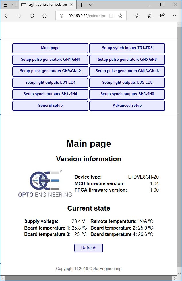
With the Ethernet interface, you can configure the controller with either the Modbus/TCP slave protocol or the internal web browser. The second option allows for a very easy configuration of the controller using a common web browser to visually change the parameters and/or inspect the device status.
LTDVE controllers allow to:
- Easily set the output current intensity of each connected illuminator in small steps
- Set the pulse duration and pulse delay of each illuminator in small steps as low as 1μs
- Control the connected illuminators with up to 8 synchronization inputs
- Control up to 8 synchronization outputs (i.e. up to 8 cameras)
- Write and save different configurations depending on your application
The LTDVE series can also be configured via the RS485 communication interface that implements the Modbus/RTU slave protocol.
The configuration is stored in a non-volatile memory to maintain your settings even when the Ethernet or RS485 connection is removed.
LTDV6CH
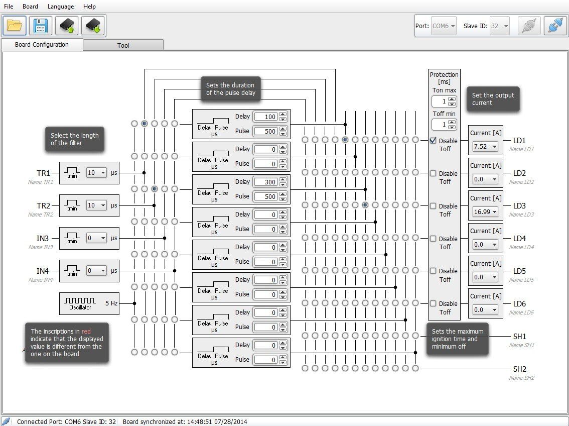
LTDV6CH can be configured via RS485. You can either download and use our free LTSW software to configure the controller from your PC or directly send low-level commands from a PC using the Modbus/RTU slave protocol (all the Modbus function codes supported by the controller are listed in the manual available online).
The LTSW software offers a very intuitive and graphical user interface where you can:
- Set the output current intensity of each connected illuminator in steps of 98 mA
- Set the pulse duration and pulse delay of each illuminator in steps of 1μs
- Control the connected illuminators with up to 4 synchronization inputs
- Control up to 2 synchronization outputs (e.g. up to 2 cameras)
- Write and save different configurations depending on your application
To use LTSW configuration software your PC must have a native RS485 communication interface or a suitable RS485/USB converter must be used (PN: ADPT001)
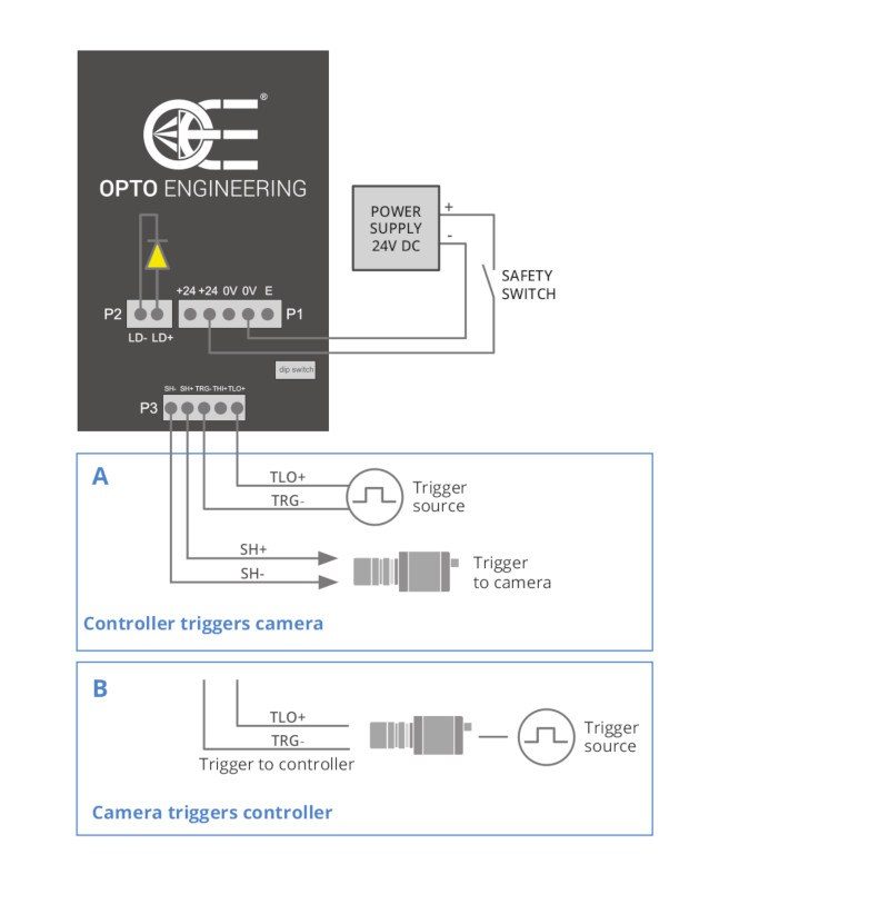
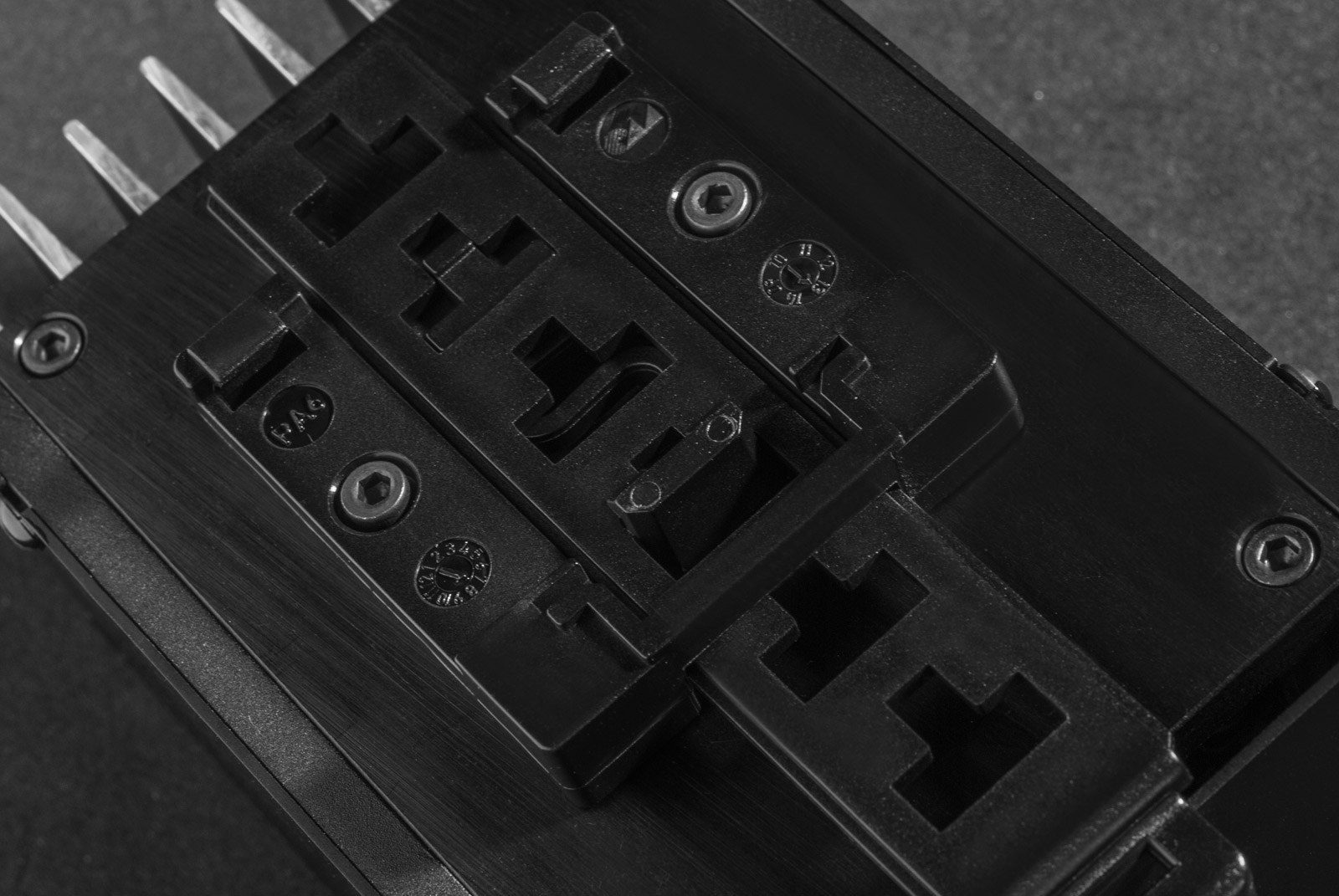
LTDV1CH-17V
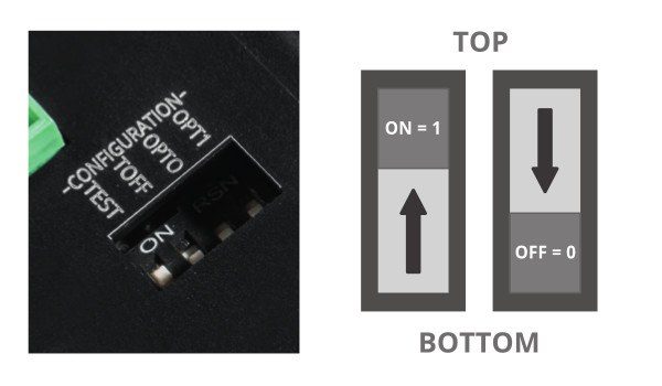
LTDV1CH-17V is simply configured from the front panel via DIP switches. You can easily set the intensity of the LED lights driving current (from 5mA to 17A), filtering option for the trigger signal (select between 10 µs or 100 µs time constant) and delay for synchronization output (select between 0 or 100 µs).
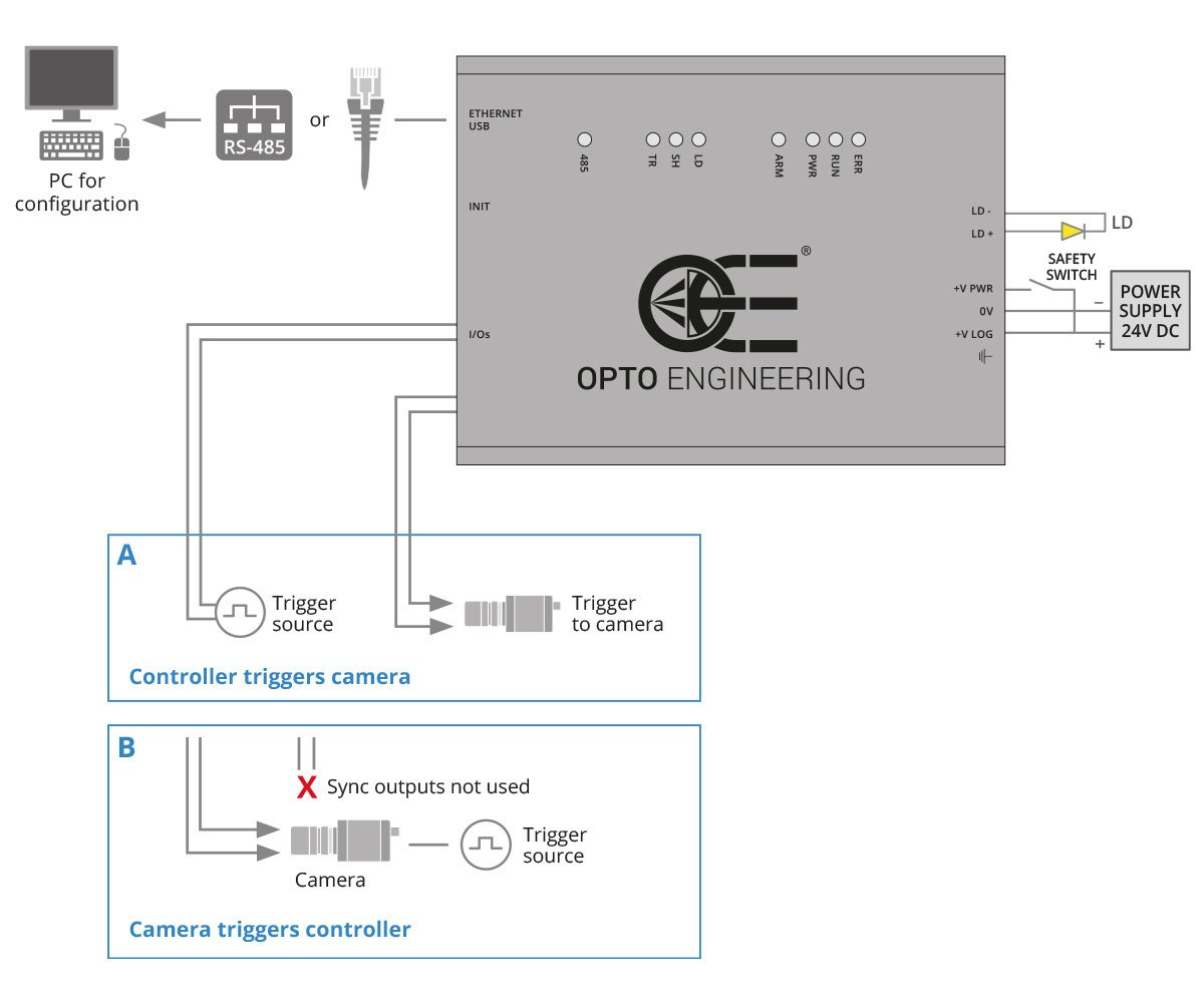
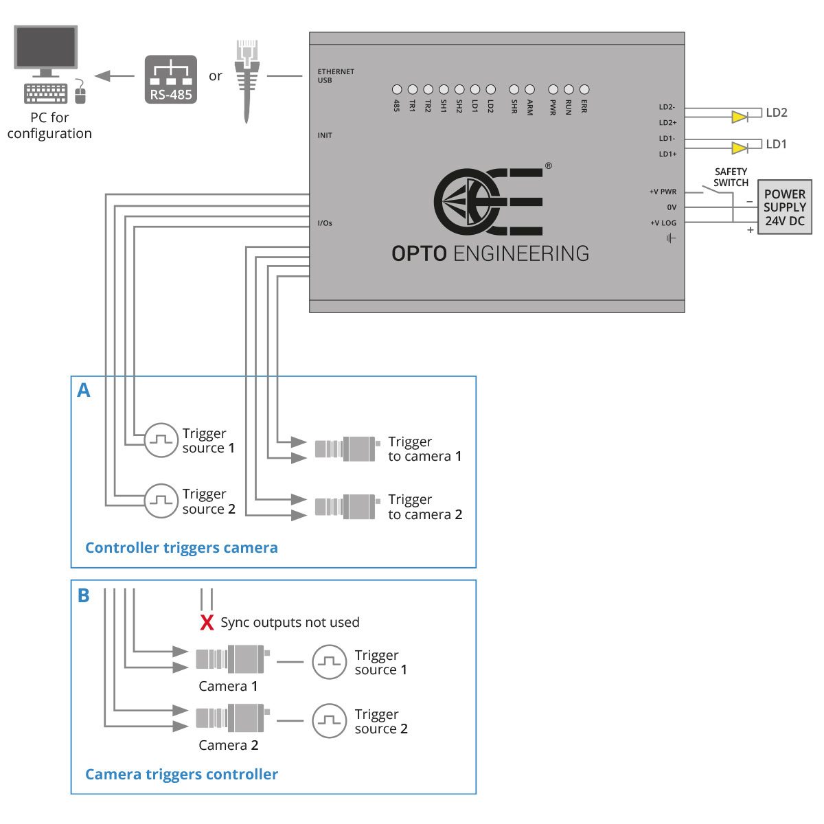
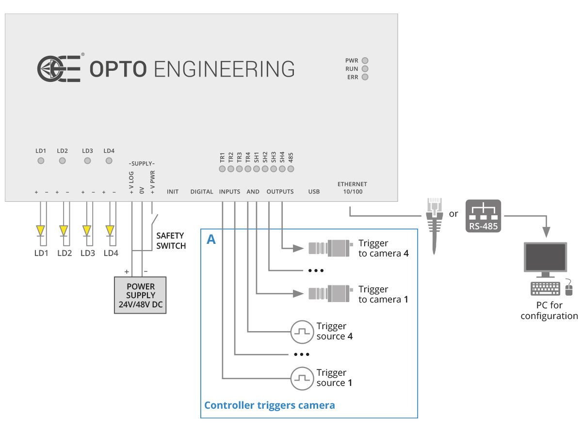
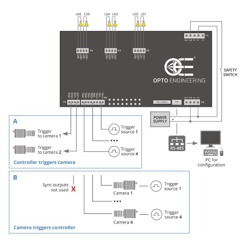
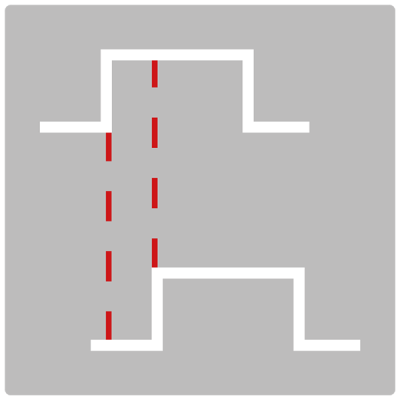
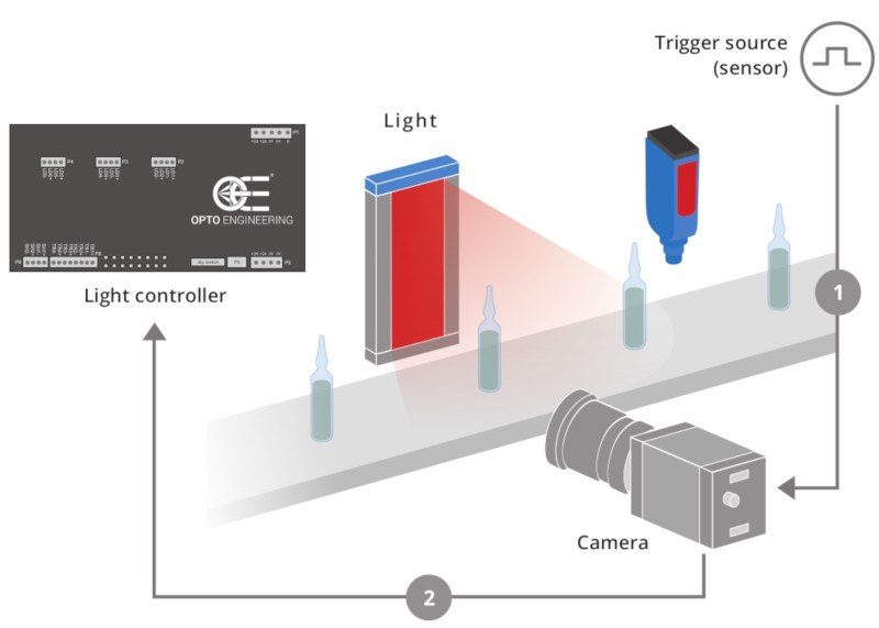
Triggering options and wiring diagrams
Two typical camera triggering arrangements (Option A and B) are illustrated for each controller model. Triggering Option A is preferred because the controller directly filters the trigger signals getting rid of unwanted noise. This configuration is possible because Opto Engineering® controllers feature dedicated synchronization outputs which are not commonly available from other manufacturers.
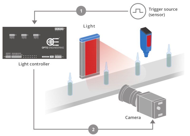
A - Controller triggers camera
Option A) shows a triggering arrangement where the light controller, once triggered by one or more trigger sources (i.e. the sensor positioned on the manufacturing line), triggers the camera(s). The advantage of such an arrangement is that the controller can filter the trigger signals before passing the command to the camera and the light.
B - Camera triggers controller
Option B) shows an arrangement where each camera is first triggered by a trigger source (i.e. the sensor positioned on the manufacturing line), and then it triggers the light controller and starts its exposure.
The following diagrams explain how to connect Opto Engineering® strobe controllers with the other machine vision components: LED lights, cameras, power supply and PC (for the configuration of all the parameters).