Home x

    Optics

  • Optics >
  • Telecentric lenses
  • Macro & Fixed focal length lenses
  • 360° view lenses
  • Infrared & UV lenses
  • Custom lenses
  • Imaging lens selector
  • Lighting

  • Lighting >
  • LED Illuminators
  • LED Pattern projectors
  • Custom lights
  • Cameras

  • Cameras >
  • Area Scan Cameras
  • Line Scan cameras
  • Camera finder
  • Customized machine vision cameras
  • Software

  • Software >
  • Machine vision software
  • Machine vision libraries
  • Accessories

  • Accessories >
  • Optical filters for lenses
  • Windows, mirrors & beamsplitters
  • Diffusing & polarizing plates for lighting
  • Calibration & resolution patterns
  • Projection patterns
  • Mounting mechanics
  • LED controllers
  • LED sources & replacements
  • Lens controllers
  • Power supplies
  • Cables
  • Others
  • AI Vision Units

  • AI Vision Units >
  • PENSO®
  • Company

  • Company >
  • Optical imaging technologies
  • Opto Engineering® for the environment
  • Who we are
  • A history of innovation
  • Committed to quality
  • Joint ventures
  • Where we are
  • Legal
  • Awards
  • Corporate videos
  • Services

    Industries

    Basics

    Resources

    Support

    Careers

    Press Review

    Contact us

    EXE Training

  • en
    • Deutsch
    • Italiano
    • 中文
Company
Services
Industries
Basics
Resources
Support
Careers
Press Review
Contact us
EXE Training
Optics
Lighting
Cameras
Software
Accessories
AI Vision Units
kits logo
Optics finder Lighting finder Camera finder
Get the right product, right from the start
  • Home
  • Optics
  • Telecentric lenses
  • TC CORE series

TC CORE series

Compact bi-telecentric lenses for sensors up to 2/3”

Opto Engineering® CATALOG

Overview
Models
Downloads
Related
Tech info
Resources

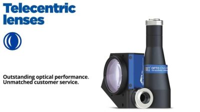
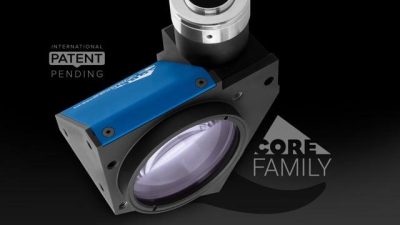
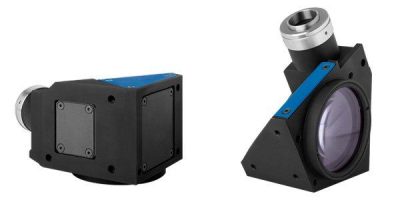
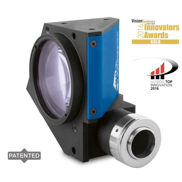
TC CORE bi-telecentric lenses for sensors up to 2/3” feature a truly revolutionary ultra compact opto-mechanical design.

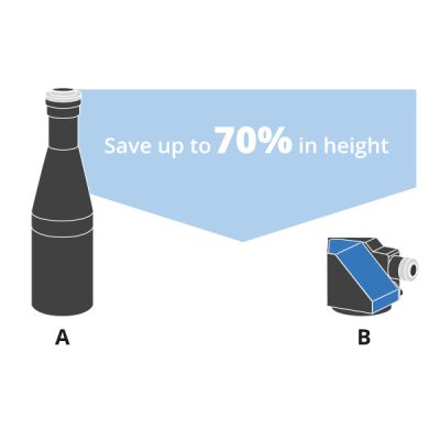
These lenses deliver high-end optical performances and at the same time are up to 70% smaller than other double-sided telecentric lenses on the market, thus allowing to significantly downsize a vision system.
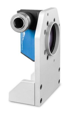
The unique shape has been expressly developed for maximum mounting flexibility.

TC CORE lenses can be mounted in different directions using any of the 4 sides even without clamps, allowing you to cut the system’s cost, and can be easily fitted or retrofitted even into very compact machines.

TC CORE bi-telecentric lenses can also be coupled with the new ultra compact LTCLHP CORE series telecentric illuminators to build super small yet extremely accurate measurement systems.

KEY ADVANTAGES

  • Excellent optical performances
    TC CORE bi-telecentric lenses deliver excellent optical performances as other comparable Opto Engineering® bi-telecentric lenses.
  • Extremely compact
    TC CORE lenses are up to 70% smaller than other telecentric lenses on the market.
  • Designed for flexibility and smart integration
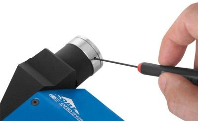
    TC CORE lenses integrate a camera phase adjustment and can be mounted on multiple sides with or without clamps, allowing you to cut the costs.
  • Save you money
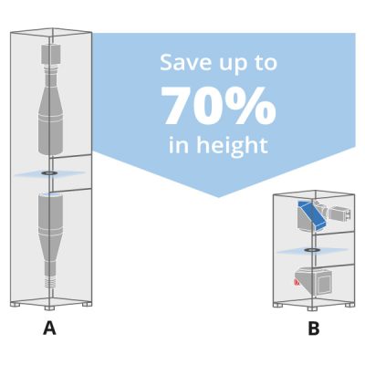
    Systems integrating TC CORE lenses take much less space,resulting in lower manufacturing, shipping and storage costs.
  • Boost your sales
    A smaller vision system or measurement machine is the solution preferred by the industry.
Comparison of a "classic" telecentric lens (A) and a TC CORE bi-telecentric lens (B): TC CORE lens delivers best optical performance and is extremely compact.
<p>
	A- Vision system featuring a classic telecentric lens and a classic telecentric illuminator <br>
	B- Vision system featuring a TC CORE bi-telecentric lens and LTCLHP CORE telecentric illuminator
</p>

A- Vision system featuring a classic telecentric lens and a classic telecentric illuminator
B- Vision system featuring a TC CORE bi-telecentric lens and LTCLHP CORE telecentric illuminator

ADVANTAGES

Cost reduction

  1. Lower manufacturing cost due to less material employed
  2. Less space required for storage and use
  3. Lower shipment expenses due to smaller size
  4. Lower transportation risks

Sell more

  1. A smaller vision system or measurement machine is preferred by the industry
UP TO 2/3" SENSORS
Mag. 0.52 - 0.184 x
TCCORE series
TC CORE series awards

TC CORE series awards

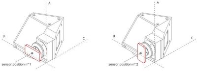
TC CORE lens dimensions (A, B, C) and correct position of the sensor in relation to the lens:

disegno_TCCORE
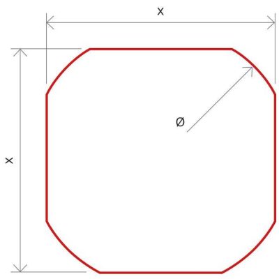
Image shape dimensions (&Oslash;, x )
Image shape dimensions (Ø, x )
Main optical specifications Object field of view Advanced optical specifications Mechanical specifications
Part
number
Magnification Image
shape
dimension
Max
sensor
size
1/3” 1/2” 2/3”
Working
distance
Working
ƒ/N
Telecentricity
typical
(max)
Distortion
typical
(max)
Field
depth
Mount Phase
adjustment
Dimension
A
Dimension
B
Dimension
C
4.80 x 3.60 6.40 x 4.80 8.50 x 7.09
(x) (mm, mm) (mm × mm) (mm × mm) (mm × mm) (mm) (deg) (%) (mm) (mm) (mm) (mm)
1 2 2 2 3 4 5 6 7 9 10 10 10
TCCR12048 0.134 Ø=8.0, x=7.1 1/2" 35.82 x 26.87 47.76 x 35.82 ø =52.91 132.9 8 < 0.07 (0.10) < 0.06 (0.10) 23.1 C Yes 77 106 111 Quote
TCCR23048 0.184 Ø=11.0, x=9.6 2/3" 26.09 x 19.57 34.78 x 26.09 46.20 x 38.53 132.9 8 < 0.08 (0.10) < 0.05 (0.10) 12.2 C Yes 77 106 131 Quote
TCCR12056 0.114 Ø=8.1, x=7.1 1/2" 42.11 x 31.58 56.14 x 42.11 ø =62.19 157.8 8 < 0.04 (0.08) < 0.04 (0.10) 31.9 C Yes 94 110 121 Quote
TCCR23056 0.157 Ø=11.1, x=9.6 2/3" 30.57 x 22.93 40.76 x 30.57 54.14 x 45.16 157.8 8 < 0.05 (0.08) < 0.03 (0.10) 16.8 C Yes 94 110 141 Quote
TCCR12064 0.100 Ø=8.4, x=6.9 1/2" 48.00 x 36.00 64.00 x 48.00 ø =69.00 181.8 8 < 0.05 (0.08) < 0.04 (0.10) 41.4 C Yes 101 122 132 Quote
TCCR23064 0.138 Ø=11.5, x=9.5 2/3" 34.78 x 26.09 46.38 x 34.78 61.59 x 51.38 181.8 8 < 0.05 (0.08) < 0.03 (0.10) 21.7 C Yes 101 122 148 Quote
TCCR12080 0.080 Ø=8.1, x=6.9 1/2" 60.00 x 45.00 80.00 x 60.00 ø =86.25 226.7 8 < 0.03 (0.08) < 0.04 (0.10) 64.7 C Yes 119 145 148 Quote
TCCR23080 0.110 Ø=11.1, x=9.6 2/3" 43.64 x 32.73 58.18 x 43.64 77.27 x 64.45 226.7 8 < 0.04 (0.08) < 0.02 (0.10) 34.2 C Yes 119 145 167 Quote
TCCR12096 0.068 Ø=8.3, x=6.8 1/2" 70.59 x 52.94 94.12 x 70.59 ø =100.00 278.6 8 < 0.06 (0.08) < 0.03 (0.10) 89.5 C Yes 139 172 183 Quote
TCCR23096 0.093 Ø=11.4, x=9.4 2/3" 51.61 x 38.71 68.82 x 51.61 91.40 x 76.24 278.6 8 < 0.06 (0.08) < 0.04 (0.10) 47.9 C Yes 139 172 192 Quote
TCCR12120 0.052 Ø=8.2, x=6.7 1/2" 92.31 x 69.23 123.08 x 92.31 ø =128.85 334.5 8 < 0.06 (0.08) < 0.08 (0.10) 153.1 C Yes 181 220 231 Quote
TCCR23120 0.072 Ø=11.2, x=9.3 2/3" 66.67 x 50.00 88.89 x 66.67 118.06 x 98.47 334.5 8 < 0.06 (0.08) < 0.08 (0.10) 79.9 C Yes 181 220 231 Quote
Last update 07 Apr 2022

Notes

  1. Indicates the dimensions and shape of image, where "Ø =" stands for diameter and "x=" indicates the nominal image height and width (Tech Info for related drawing).
  2. Object field of view (mm x mm). For the fields with the indication "Ø =", the image of a circular object of such diameter is fully inscribed into the sensor.
  3. Working distance: distance between the front end of the mechanics and the object. Set this distance within ±3% of the nominal value for maximum resolution and minimum distortion.
  4. Working f-number (wf/N): the real f-number of a lens in operating conditions.
  5. Maximum angle between chief rays and optical axis on the object side. Typical (average production) values and maximum (guaranteed) values are listed.
  6. Percent deviation of the real image compared to an ideal, undistorted image. Typical (average production) values and maximum (guaranteed) values are listed.
  7. At the borders of the field depth the image can be still used for measurement but, to get a very sharp image, only half of the nominal field depth should be considered. Pixel size used for calculation is 3.45 μm.
  8. Object side, calculated with the Rayleigh criterion with λ= 520 nm
  9. Indicates the availability of an integrated camera phase adjustment feature.
  10. Due to the special shape of TCCR120xx it might be necessary to check the mechanical compatibility with your camera

Technical documents

Product user guide
pdf
Back focal adjustment
pdf

Press & marketing content

Metrology white paper
pdf
spinner

Take a look at our wide selection of area scan cameras

COE-x group cameras

COE-G series

GenICam® PoE C-mount cameras
COE-x group cameras

COE-U series

GenICam® C-mount USB3 cameras

Find the perfect matching light

LTCLHP CORE series

LTCLHP CORE series

Compact telecentric illuminators
LTCLCP23144_main_front.jpg

LTCLHP CORE PLUS series

Compact telecentric illuminators for large FOV systems
LT2BC_family

LT2BC series

High uniformity continuous LED backlights

Discover our high-performance machine vision software

Machine vision software and libraries

FabImage® Studio Professional

Software for Machine Vision Engineers
Software library & stand-alone tools for the optimization of telecentric optics setups

TCLIB Suite

Software library & stand-alone tools for the optimization of telecentric setups
Windows OS desktop application for optical measurement

Horus

Windows OS desktop application for optical measurement

Some accessories you might be interested in

Telecentric lens filters

OPFI series

Filters for telecentric lenses and fixed focal length lenses
Calibration pattern series

PTTC, PTCP series

Accurate calibration patterns for machine vision
CMHOCR_serie

CMHOCR series

Clamping mechanics for CORE lenses

If you are looking for larger FoV compact solutions

TCCP23144_main_front.jpg

TC CORE PLUS series

Compact large-FOV bi-telecentric lenses for sensors up to 2/3”

Video gallery

Find more videos on our Vimeo channel

Product images

Application examples

Off-line precision measurement systems

Press & marketing content

Metrology white paper
pdf
Company & Resources
Optical imaging technologies Opto Engineering® for the environment Who we are A history of innovation Committed to quality Joint ventures Where we are Legal Awards Corporate videos 2D and 3D models Image gallery Video gallery Search OE products by applications Application notes Basics Frequently asked questions Press Review Jobs at Opto Engineering®
  • Opto Engineering Copyright © 2015 - 2022 - VAT IT02011230204
  • Fiscal code and registration number at Mantova Business Register 02011230204, Nr. REA: MN-216669, Share Capital: 200.000,00 €
  • All rights reserved - Terms of use - Use of cookies & privacy policy
  • Design & development by Opto Engineering® → SEO and consulting by Dipiemme Studio

Follow us


WE ARE CERTIFIED

  • TuvRheinald Certified
  • This website is hosted Green - checked by thegreenwebfoundation.org
  • ENWHP Rete Lombardia

ASSOCIATIONS WE SUPPORT

  • ANIE Automazione
  • Vision Markets - Machine Vision business consulting
  • Member of EMVA - European Machine Vision Association