Homex

    Optics

  • Optics >
  • Telecentric lenses
  • Macro & Fixed focal length lenses
  • 360° view lenses
  • Infrared & UV lenses
  • Custom lenses
  • Imaging lens selector
  • Lighting

  • Lighting >
  • LED Illuminators
  • LED Pattern projectors
  • Custom lights
  • Cameras

  • Cameras >
  • Area Scan Cameras
  • Line scan cameras
  • Camera finder
  • Customized machine vision cameras
  • Software

  • Software >
  • Machine vision software
  • Machine vision libraries
  • Accessories

  • Accessories >
  • Optical filters for lenses
  • Windows, mirrors & beamsplitters
  • Diffusing & polarizing plates for lighting
  • Calibration & resolution patterns
  • Projection patterns
  • Mounting mechanics
  • LED controllers
  • LED sources & replacements
  • Lens controllers
  • Power supplies
  • Cables
  • Others
  • AI Vision Units

  • AI Vision Units >
  • ALBERT®
  • PENSO®
  • Company

  • Company >
  • Optical imaging technologies
  • OE for the future
  • Who we are
  • A history of innovation
  • Committed to quality
  • Joint ventures
  • Where we are
  • Legal
  • Product awards
  • Corporate videos
  • Services

    Industries

    Basics

    Resources

    Support

    Careers

    Press Review

    Contact us

    EXE Training

Empty cart
  • en
    • Deutsch
    • Italiano
    • 中文
Company
Services
Industries
Basics
Resources
Support
Careers
Press Review
Contact us
EXE Training
Optics
Lighting
Cameras
Software
Accessories
AI Vision Units
kits logo
  • Home
  • Accessories
  • LTDV series

LTDV series

LED lighting strobe controllers

Opto Engineering® CATALOG

LTDV1CH-7 and LTDV1CH-17 have been discontinued and replaced by LTDV1CH-17V. Contact our sales engineers to discuss any specific need.
Overview
Models
Downloads
Related
Tech info
Media gallery

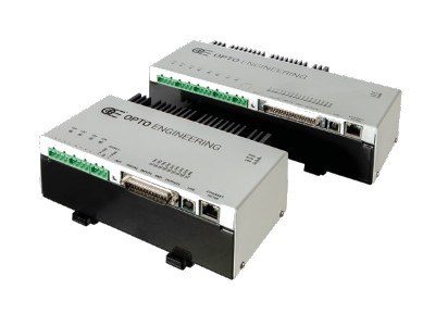
Opto Engineering® range of strobe controllers offer repeatable fast pulsing for quick and accurate strobing of a wide variety of LED lightings available today.

The LTDV series comprises models with up to eight channels either with Ethernet and/or R485 interfaces and a single channel controller with analogue interface.

Opto Engineering® strobe controllers include LTDVE8CH-20 and LTDVE4CH-20 with Ethernet and RS485 interfaces featuring respectively eight and four output channels driving lights with currents up to 20A (pulsed) and 2A (continuous), LTDV6CH featuring six channels and RS485 interface to drive lights up to 17A (pulsed) and LTDV1CH featuring one single channel, simple DIP switch interface and designed to drive lights with currents from 5mA up to 17A.

LTDV controllers accurately set current intensity, pulse duration and delay of LED illuminators, they offer filtering options for trigger signals and easily synchronize the strobe pulses with the camera exposure to meet today’s machine vision high speed demands.

These controllers are designed to get the very best out of Opto Engineering® LED lighting solutions, in terms of both brightness stability and precise control.

KEY ADVANTAGES

  • Compatible with most of the LED lighting solutions available.
  • Ethernet, RS485 interface.
  • Up to 8 independently controlled output channels.
  • Max output current up 20A pulsed.
  • Easy configuration.
  • Small, compact unit with DIN rail mounting.

NEW LTDVE2CH-20F model

LED Strobe controller 2 channels, 20A/40A pulsed - 2A/4A continuous

Strobe controllers
Part number LTDV1CH-17V LTDVE2CH-20F LTDVE4CH-20 LTDV6CH LTDVE8CH-20
Electrical specifications
Status LEDs Yes (for power on and trigger) Yes (for all I/Os)
User interface 12-way dip switchEthernet 100 Mbps
(using a Web browser or Modbus/TCP slave or Modbus/UDP slave)
RS485 (via Modbus/RTU slave)
Ethernet 100 Mbps
(using a Web browser or Modbus/TCP slave or Modbus/UDP slave)
RS485 (via Modbus/RTU slave)
RS485 (via Modbus/RTU slave)Ethernet 100 Mbps
(using a Web browser or Modbus/TCP slave or Modbus/UDP slave)
RS485 (via Modbus/RTU slave)
Configuration software ---LTSW included-
Output channels n° 1 constant current output2 indipendent
constant current output
4 indipendent
constant current output
6 independent constant current outputs8 indipendent
constant current output
Output current range 2 (A) 5 mA-160 mA (in steps of 5 mA) pulsed or continuous
100 mA-3.2 A (in steps of 100 mA) pulsed
1.5 A-17 A (in steps of 500 mA) pulsed
2 independent channels: Pulsed up to 20A per channel,
Continuous up to 2A per channel
1 shared channel: Up to 40A Pulsed or 4A Continuous
Up to 20A pulsed or 2A continuous
(in steps of 1mA from zero to 200mA,
4mA from 201mA to 4000mA
and 20mA from 4001mA to 20A)
3.5A - 17.0 pulsed
(in steps of 98 mA)
Up to 20A pulsed or 2A continuous
(in steps of 1mA from zero to 200mA,
4mA from 201mA to 4000mA
and 20mA from 4001mA to 20A)
Max dissipable thermal power per channel (W) 84454
Synchronization inputs n° 1 opto-isolated digital input2 opto-isolated digital input (1)4 opto-isolated digital input (1)4 opto-isolated digital inputs (1)8 opto-isolated digital input (1)
Synchronization outputs n° 1 opto-isolated digital output2 opto-isolated digital output4 opto-isolated digital output2 opto-isolated digital outputs8 opto-isolated digital output
Pulse delay (μs) -0 - 1.000.000 (2)0 - 1.000.000 (2)0 - 65535 (3)0 - 1.000.000 (2)
Pulse width (μs) -2 - 1.000.000 (2)10 - 1.000.000 (2)10 - 65535 (3)10 - 1.000.000 (2)
Timing repeatability for pulse delay (μs) -0.1 (4)0.1 (4)0.1 (4)0.1 (4)
Timing repeatability for pulse width (μs) -0.1 (4)0.1 (4)0.1 (4)0.1 (4)
Supply voltage (V, DC) 24 (5)2424 - 48 24 524 - 48
Output voltage (V) 0 - 12 (with step-up disabled)
or 0 - 36 (with step-up enabled
5 - 1950 - 360 - 360 - 36
Mechanical specifications
Dimensions 6
Length (mm) 70128195(6)205255 (6)
Heigth (mm) 825075 (6)8475 (6)
Width (mm) 119120135 (6)123135 (6)
Mounting DIN rail4 fixing slotsDIN railDIN railDIN rail
Accessories ---ADPT001 7-
Compatible products Compatible with most LED lightings availableCompatible with most LED lightings availableCompatible with most LED lightings availableLTDM series, LTLA series,
LTDMLA series, View-through system
Compatible with most LED lightings available
Buy nowBuy nowBuy nowBuy nowBuy now

Last update: 2020-09-18

Notes

  1. Operate from 3.3V to 24V
  2. In variable resolution depending on selected value
  3. In steps of 1 μs.
  4. Digital processing/li>
  5. Regulated ± 10%.
  6. Including DIN fixing.
  7. To be ordered separately. ADPT001 consists of - one RS485-USB adapter and - one cable for connection with LTDV6CH. In order to configure LTDV6CH via software a RS485 port must be provided.

Technical documents

Data table (Last update: :2020-09-18)
XLS
LTDVE2CH-20F_manual_V1.04_2021-02-19.pdf
LTDV6CH manual V3.0
LTDV1CH manual
LTDVE4CH-20_manual_V1.13_2021-02-19.pdf
LTDVE8CH-20_manual_V1.12_2021-02-19.pdf
LTDV1CH-17V manual V2.1
LTDV1CH-7-17 manual V2.0

Software tools

LTDV LTIC Library v1.03
LTSW configuration software

Press & marketing content

OE products for Pharma & Medical Industries
pdf
spinner

Compatible products

Screenshot of LTSW configuration software

LTSW software

Strobe controller configuration software for LTDV6CH

See also

LTDM series
LTLA series
LTDMLA series
View-through system

Easy configuration

Easily configure and manage strobe, trigger and camera signals.


LTDVExCH-20

Opto Engineering® LTDVE series of controllers can be configured via Ethernet or RS485.

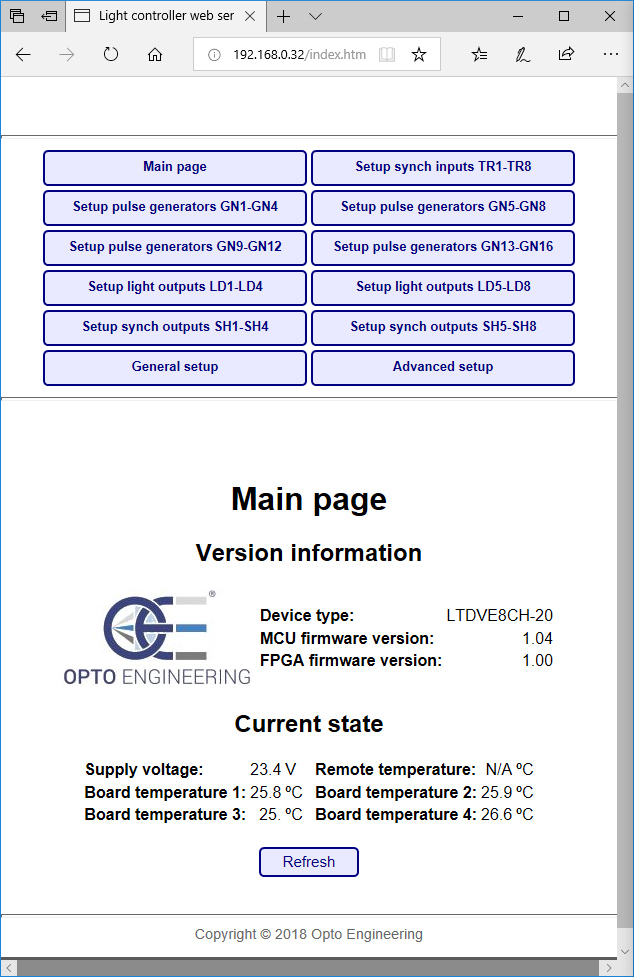
With the Ethernet interface, you can configure the controller with either the Modbus/TCP slave protocol or the internal web browser. The second option allows for a very easy configuration of the controller using a common web browser to visually change the parameters and/or inspect the device status.

  • Easily set the output current intensity of each connected illuminator in small steps
  • Set the pulse duration and pulse delay of each illuminator in small steps as low as 1μs
  • Control the connected illuminators with up to 8 synchronization inputs
  • Control up to 8 synchronization outputs (e.g. up to 8 cameras)
  • Write and save different configurations depending on your application

The LTDVE series can also be configured via the RS485 communication port interface that implements the Modbus/RTU slave protocol.

The configuration is stored in a non-volatile memory to maintain your settings even when the Ethernet or RS485 connection is removed.

Main page of LTDVE configuration software via browser

Main page of LTDVE configuration software via browser

LTDV6CH

LTDV6CH can be configured via RS485. You can either download and use our free LTSW software to configure the controller from your PC or directly send low-level commands from a PC using the Modbus/RTU slave protocol (all the Modbus function codes supported by the controller are listed in the manual available online).

The LTSW software offers a very intuitive and graphical user interface where you can:

  • Set the output current intensity of each connected illuminator in steps of 98 mA
  • Set the pulse duration and pulse delay of each illuminator in steps of 1μs
  • Control the connected illuminators with up to 4 synchronization inputs
  • Control up to 2 synchronization outputs (e.g. up to 2 cameras)
  • Write and save different configurations depending on your application

To use LTSW configuration software your PC must have a native RS485 communication interface or a suitable RS485/USB converter must be used (PN: ADPT001) .

Main control panel of configuration software

Main control panel of configuration software


LTDV1CH

LTDV1CH is simply configured from the front panel via DIP switches. You can easily set the intensity of the LED lights driving current (from 5mA to 17A), filtering option for the trigger signal (select between 10 μs or 100 μs time constant) and delay for synchronization output (select between 0 or 100 μs).

DIP switches interface for simple and fast configuration

DIP switches interface for simple and fast configuration


Triggering options and wiring diagrams

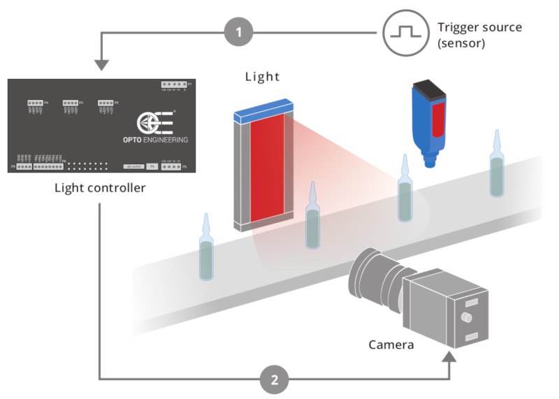
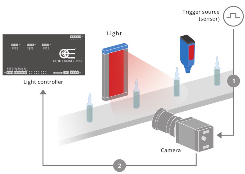
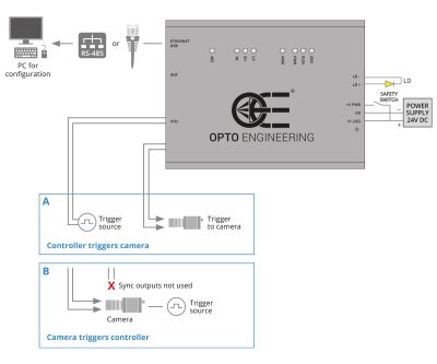
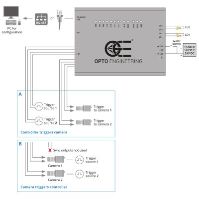
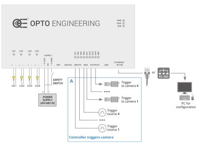
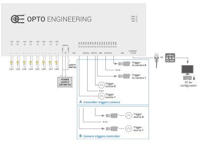
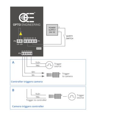
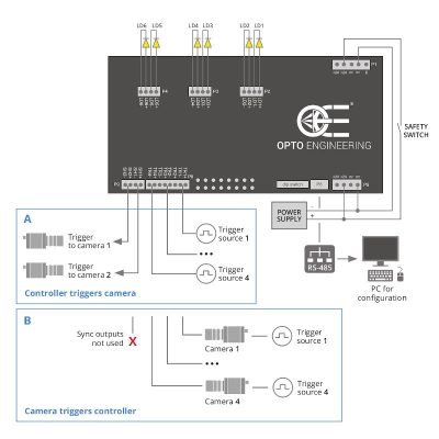
Two typical camera triggering arrangement (Option A and B) are illustrated for each controller model. Triggering Option A) is preferred because the controller directly filters the trigger signals getting rid of unwanted noise. This configuration is possible because Opto Engineering® controllers feature dedicated synchronization outputs which are not commonly available from other manufacturers.

A - Controller triggers camera

Option A - shows a triggering arrangement where the light controller is triggered by trigger source(s) (sensor positioned on the manufacturing line) and the lighting controller then triggers the camera(s). This arrangement has the advantage that the controller can filter the trigger signals before passing the command to the camera and the light.

Controller triggers camera option A

B - Camera triggers controller

Option B - shows an arrangement where each camera is triggered by a trigger source (sensor), the camera then triggers the light controller and starts its exposure.

Controller triggers camera option B

The following diagrams explain how to connect Opto Engineering® strobe controllers with the other machine vision components: LED lights, cameras, power supply and PC (for the configuration of all the parameters).

LTDV1CH-17v

Setup controller

LTDV6CH

The following diagrams explain how to connect Opto Engineering® strobe controllers with the other machine vision components

LTDVE2CH-20F

The following diagrams explain how to connect Opto Engineering® strobe controllers with the other machine vision components

LTDVE4CH-20

Setup controller

LTDVE8CH-20

Setup controller

Find more videos on our Vimeo channel

Product images

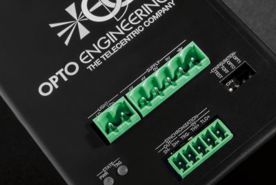
  • LTDV
  • LTDV
  • LTDV
Company & Resources
Optical imaging technologies OE for the future Who we are A history of innovation Committed to quality Joint ventures Where we are Legal Product awards Corporate videos 2D and 3D models Image gallery Video gallery Search OE products by applications Application notes Basics Frequently asked questions Press Review Jobs at Opto Engineering
  • Opto Engineering Copyright © 2015 - 2021 - VAT IT02011230204
  • Fiscal code and registration number at Mantova Business Register 02011230204, Nr. REA: MN-216669, Share Capital: 200.000,00 €
  • All rights reserved - Terms of use - Use of cookies & privacy policy
  • Design & development by Opto Engineering® → SEO and consulting by Dipiemme Studio

Follow us


WE ARE CERTIFIED

  • ENWHP Rete Lombardia
  • ISO 9001:2015
  • TuvRheinald Certified
  • This website is hosted Green - checked by thegreenwebfoundation.org

ASSOCIATIONS WE SUPPORT

  • Vision Markets - Machine Vision business consulting