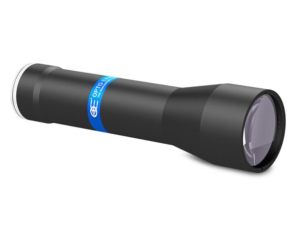
TCLWD3M series
Fixed working distance telecentric lenses for sensors up to 1.1”

Key advantages
- Wide image circle for sensors up to 1.1”
- Fixed working distance
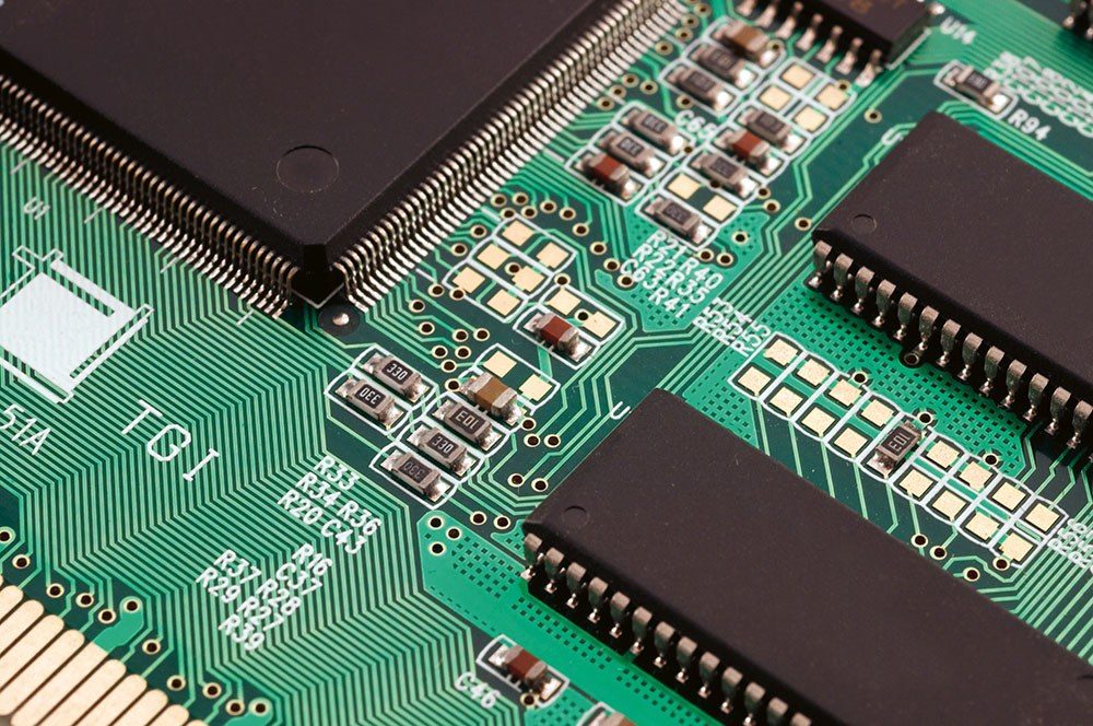
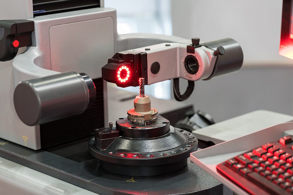
Perfect for electronic components inspection and tool pre-setting machines. - High numerical aperture
For small pixel size / high resolution detectors. - Excellent quality/price ratio
TCLWD3M series is a range of high resolution telecentric lenses specifically designed for electronic and semiconductor Automated Optical Inspection (AOI) and tool pre-setting machines. The long working distance allows for extra space, which is essential if you need to install illumination, pick-up tools or provide the necessary separation from hazardous production processes.
TCLWD3M lenses have been optimized to match up to the new 1.1” Sony sensor in order to deliver high resolution and superb image quality.
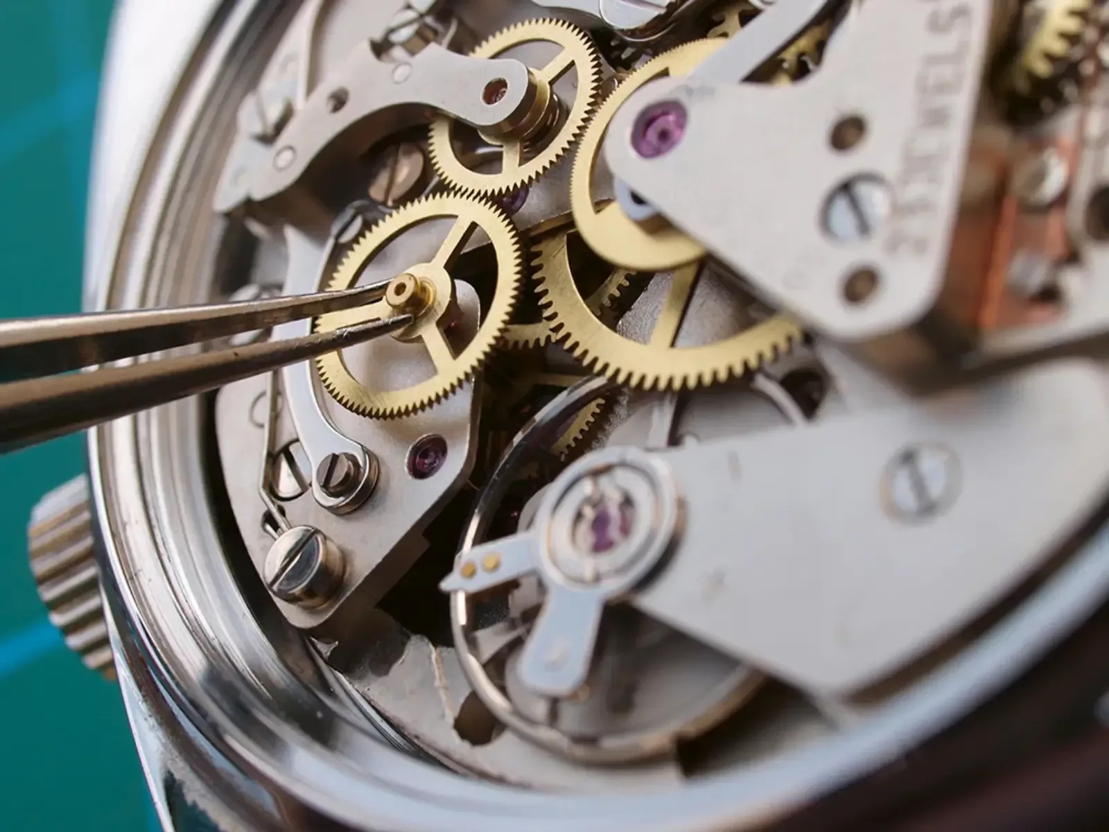
In addition to the long working distance, TCLWD3M optics deliver a numerical aperture large enough to take advantage of high resolution / small pixel size cameras, making these lenses a perfect match for general-purpose 2D measurement systems.

Notes
- Object field of view (mm x mm). For the fields with the indication "Ø =", the image of a circular object of such diameter is fully inscribed into the detector.
- Working distance: distance between the front end of the mechanics and the object. Set this distance within ±3% of the nominal value for maximum resolution and minimum distortion.
- Working f-number (wf/N): the real f-number of a lens in operating conditions.
- Maximum angle between chief rays and optical axis on the object side. Maximum (guaranteed) values are listed.
- Percent deviation of the real image compared to an ideal, undistorted image.
- At the borders of the field depth the image can be still used for measurement but, to get a very sharp image, only half of the nominal field depth should be considered. Pixel size used for calculation is 3.45 μm.
- Object side, calculated with the Rayleigh criterion with λ= 520 nm
- Measured from the front end of the mechanics to the camera flange.
Video gallery


