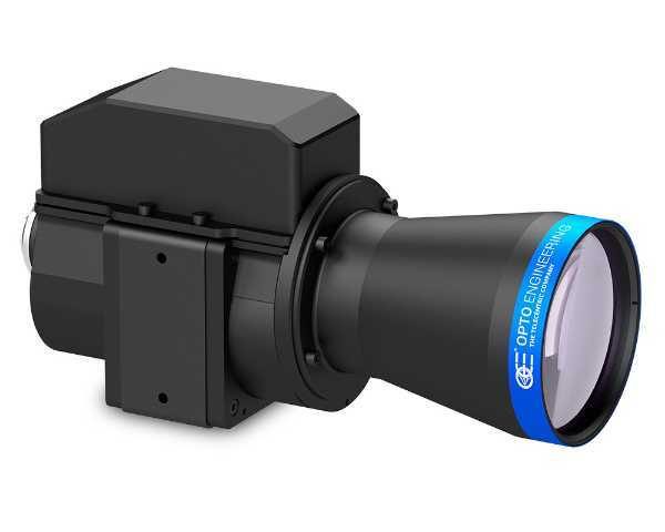
TCZRS series
Bi-telecentric zoom lenses with motorized control

Key advantages
- Perfect magnification constancy and parfocality
No need to recalibrate or refocus after zooming thanks to an extremely precise positioning system - Bi-telecentricity
For very accurate measurement - Excellent image centre stability
Image centring is maintained at every magnification - Full motorization control
Zoom magnification is set via software - Fast and silent operations
Max 2 seconds to softly switch from one mag to another - Detailed test report with measured optical parameters
TCZRS series is a leading edge optical solution for imaging and measurement applications requiring both the flexibility of zoom lenses and the accuracy of fixed optics.
An upgraded version of TCZR lenses, the newly designed TCZRS lenses feature an extremely precise positioning system with a bipolar stepper motor and an incremental magnetic encoder, delivering exceptional magnification repeatability. Moreover, focusing and image-centering stability are guaranteed at every magnification position, thus avoiding recalibration at any given time.
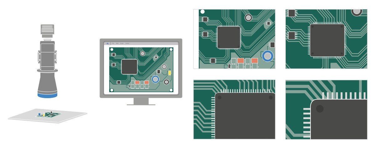
Four different magnifications, featuring a total zoom range of 8x, can be selected through a dedicated remote control software.
Bi-telecentricity, high resolution and low distortion make these zoom lenses able to perform the same measurement tasks as classic telecentric lenses.
Application examples
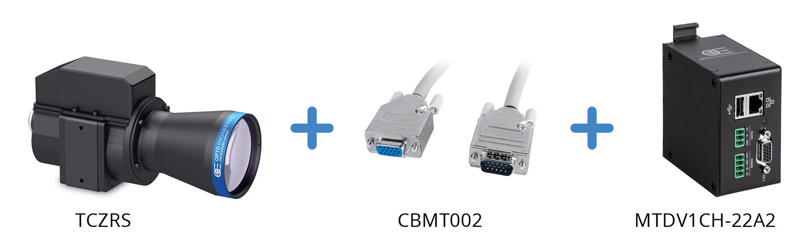
Product combinations
To be ordered separately.
Features
Notes
- Working distance: distance between the front end of the mechanics and the object. Set this distance within ±3% of the nominal value for maximum resolution and minimum distortion.
- Working f-number (wf/N): the real f-number of a lens in operating conditions.
- Maximum angle between chief rays and optical axis on the object side. Typical (average production) values and maximum (guaranteed) values are listed.
- Percent deviation of the real image compared to an ideal, undistorted image. Typical (average production) values and maximum (guaranteed) values are listed.
- At the limits of the depth of field, the image can still be used for measurements. For a very sharp image, however, only half of the depth of field should be considered. Pixel size used for calculation is 3.45 μm.
- Object side, calculated with the Rayleigh criterion with λ= 520 nm
- Image side, at 1 σ standard deviation.
- Image side.
- One magnification step.
- Two magnification steps.
- 1 encoder pulse = 2.56 motor µsteps (with a 256 microstepping control).
- Indicates the availability of an integrated camera phase adjustment feature
Download configuration file
Type the S/N serial number reported on the lens to download the configuration file.
Video gallery


