Specifications
Downloads
Compatible products
| Main optical specifications | ||
| Magnification | (x) | 0.500 |
| Image circle diameter | (mm) | 17.6 |
| Max sensor size | 1.1″ | |
| Object field of view | ||
| 1/2.5” - 5.70 x 4.28 (1) | (mm × mm) | 11.40 x 8.56 |
| 1/1.8” - 7.13 x 5.33 (1) | (mm × mm) | 14.26 x 10.66 |
| 2/3” - 8.50 x 7.09 (1) | (mm × mm) | 17.00 x 14.18 |
| 1″ - 14.19 x 7.51 (1) | (mm × mm) | 28.38 x 15.02 |
| 1.1″ - 14.16 x 10.37 (1) | (mm × mm) | 28.32 x 20.74 |
| Advanced optical specifications | ||
| Working distance (2) | (mm) | 178 |
| Working ƒ/N (3) | 10 | |
| Telecentricity (4) | (deg) | < 0.25 |
| Distortion (5) | (%) | < 0.15 |
| Depth of field (6) | (mm) | 2.10 |
| Resolution (7) | (μm) | 13 |
| Mechanical specifications | ||
| Mount | C | |
| Phase adjustment | Yes | |
| Length (8) | (mm) | 193 |
| Front diameter | (mm) | 52 |
| Mass | (g) | 415 |
Last update 08 Nov 2024
Notes
- Object field of view (mm x mm). For the fields with the indication "Ø =", the image of a circular object of such diameter is fully inscribed into the detector.
- Working distance: distance between the front end of the mechanics and the object. Set this distance within ±3% of the nominal value for maximum resolution and minimum distortion.
- Working f-number (wf/N): the real f-number of a lens in operating conditions.
- Maximum angle between chief rays and optical axis on the object side. Maximum (guaranteed) values are listed.
- Percent deviation of the real image compared to an ideal, undistorted image.
- At the borders of the field depth the image can be still used for measurement but, to get a very sharp image, only half of the nominal field depth should be considered. Pixel size used for calculation is 3.45 μm.
- Object side, calculated with the Rayleigh criterion with λ= 520 nm
- Measured from the front end of the mechanics to the camera flange.
All product specifications and data are subject to change without notice to improve reliability, functionality, design or other. Photos and pictures are for illustration purposes only.
Despite the efforts made to generate an error-free compatibility list, we always recommend to consult the Opto Engineering® technical support department before purchasing a compatible product. Opto Engineering® shall not be liable for any damage or malfunctioning caused by the incorrect selection of a compatible product.

ITA120-GM-10C
Area scan camera 4112 x 3008 MP, Sony IMX304, CMOS Global shutter, 1.1", Mono, 1 GigE, POE, C mount
ITA120-GC-10C
Area scan camera 4112 x 3008 MP, Sony IMX304, CMOS Global shutter, 1.1", Color, 1 GigE, POE, C mount
ITA120-GM-11C-PL
Area scan camera 4112 x 3008 MP, Sony IMX253, CMOS Global shutter, 1.1", Polar Mono, 1 GigE, POE, C mount
ITA120-GC-11C-PL
Area scan camera 4112 x 3008 MP, Sony IMX253, CMOS Global shutter, 1.1", Polar Color, 1 GigE, POE, C mount
ITA162-GM-20C
Area scan camera 5328 x 3040 MP, Sony IMX542, CMOS Global shutter, 1.1", Mono, 1 GigE, POE, C mount
ITA162-GC-20C
Area scan camera 5328 x 3040 MP, Sony IMX542, CMOS Global shutter, 1.1", Color, 1 GigE, POE, C mount
ITA204-GM-20C
Area scan camera 4512 x 4512 MP, Sony IMX541, CMOS Global shutter, 1.1", Mono, 1 GigE, POE, C mount
ITA204-GC-20C
Area scan camera 4512 x 4512 MP, Sony IMX541, CMOS Global shutter, 1.1", Color, 1 GigE, POE, C mount
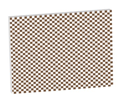
PT016-024
Calibration pattern
PT016-024-C
Checkerboard calibration pattern for telecentric lens with certificate
Request a quote
Add this product to the quote request list.
Product images