TCCAGE series
Bi-telecentric system for multiple side imaging and measurement at 90°
Extended range New TCCAGE models now available with higher resolution and high power illumination

Key advantages
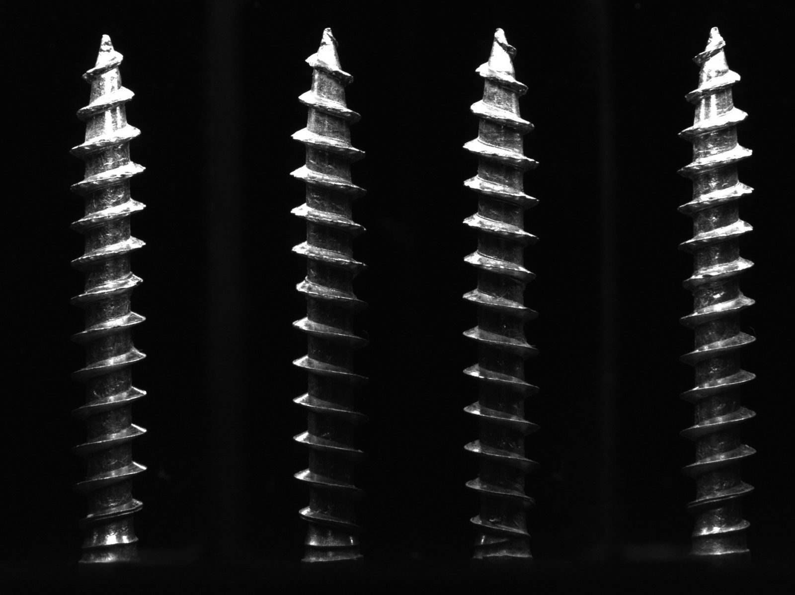
- 90° lateral imaging
the 4 orthonormal views allow visualization of object features that are hidden when looked at from the top - Long and thin object inspection
the characteristic aspect ratio of the four image segments perfectly fits long and thin objects - Built-in illumination
the device also incorporates two different light sources, for back and direct illumination - Suitable for measurement
the telecentric lens makes this module perfect for any multiple-measurement application.
Real-world application examples and case histories
Notes
- Recommended sensor. Different sensor sizes may generate incomplete images.
- Maximum sample diameter in each of the four views and maximum sample height with the recommended sensor.
- Working f-number (wf/N): the real f-number of a lens in operating conditions. Lenses with reduced aperture can be supplied on request.
- At the limits of the depth of field, the image can still be used for measurements. For a very sharp image, however, only half of the depth of field should be considered. Pixel size used for calculation is 3.45 μm.
- Tolerance ± 2%.
- Drop to 50% intensity @ 25°C.
- Indicates the availability of an integrated camera phase adjustment feature.
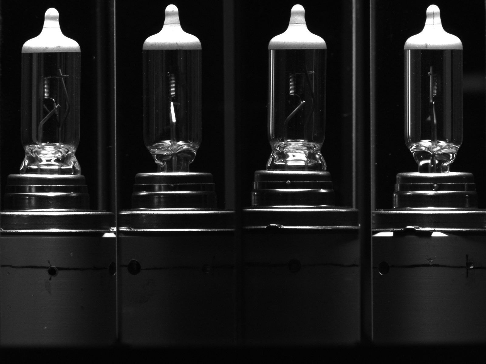
Working principle
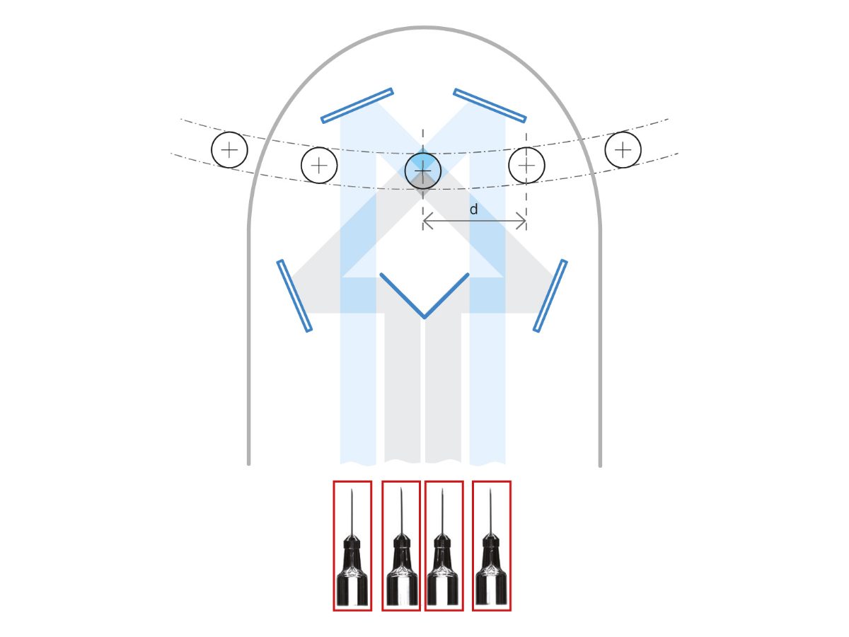
A bi-telecentric lens observes the object from four different positions through a mirror assembly, ensuring that the optical path is the same for all four view points.
The four views are equally spaced by 90° and partially overlapped, obtaining complete coverage of the object's lateral surfaces.
The system can thus tolerate off-centred components without any significant decay of the image quality thanks to the telecentric lens, which ensures that magnification is maintained in each image segment. The system is designed so as to allow components to pass unobstructed through the mirror cage, for inline applications.
When TCCAGE system is used for inline inspection, consider the following minimum distance “d” between two consecutive objects in order to avoid image overlapping:
TCCAGExx048 d (mm) ≅ 25 + ∅ object / 2
TCCAGExx096 d (mm) ≅ 50 + ∅ object / 2
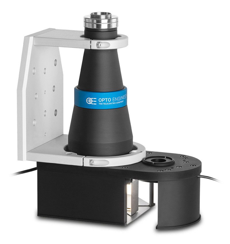
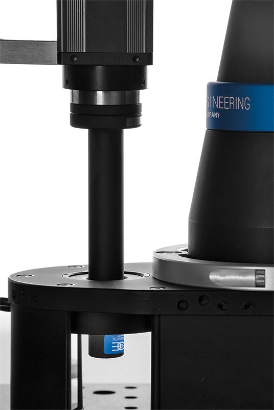
Additional port
TCCAGE is provided with an extra port placed right above the object. This port can be used to inspect the top of the part using an additional lens and camera system (for example a PCHI hole inspection lens, a macro or TC lens). The port can also house other types of illuminators.
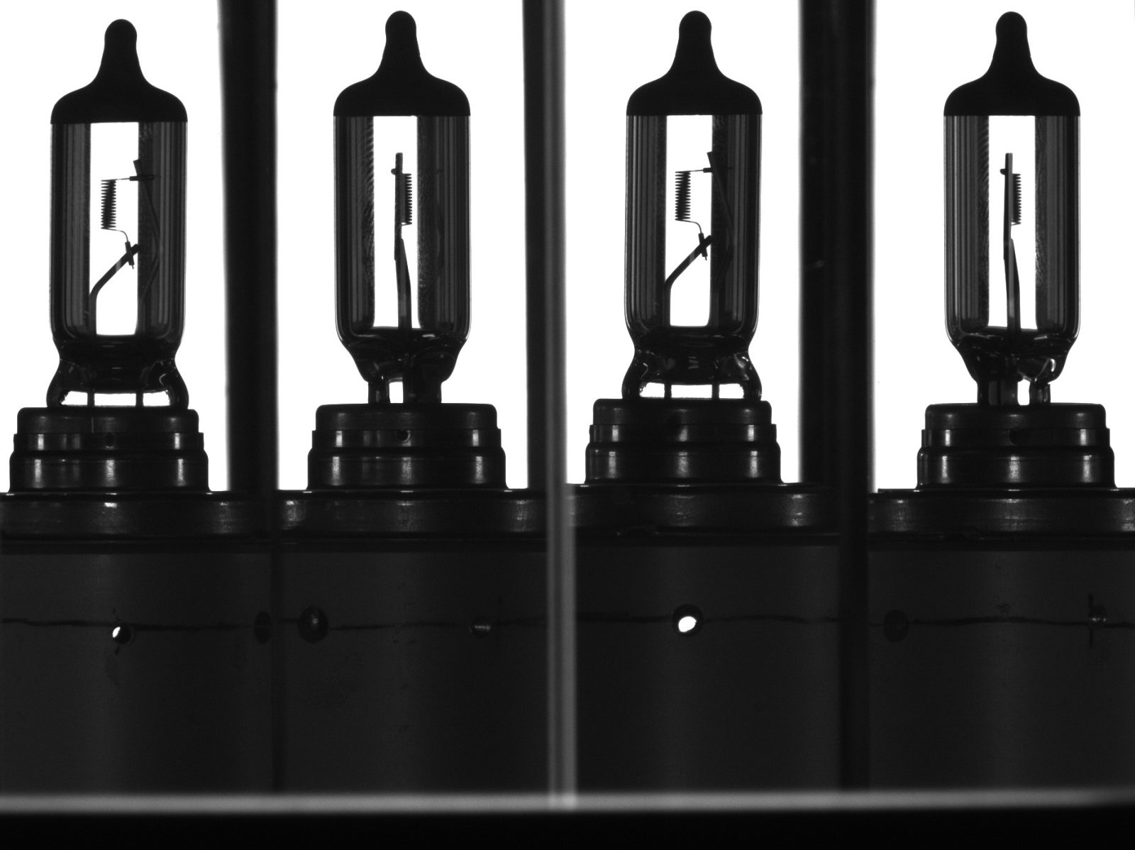
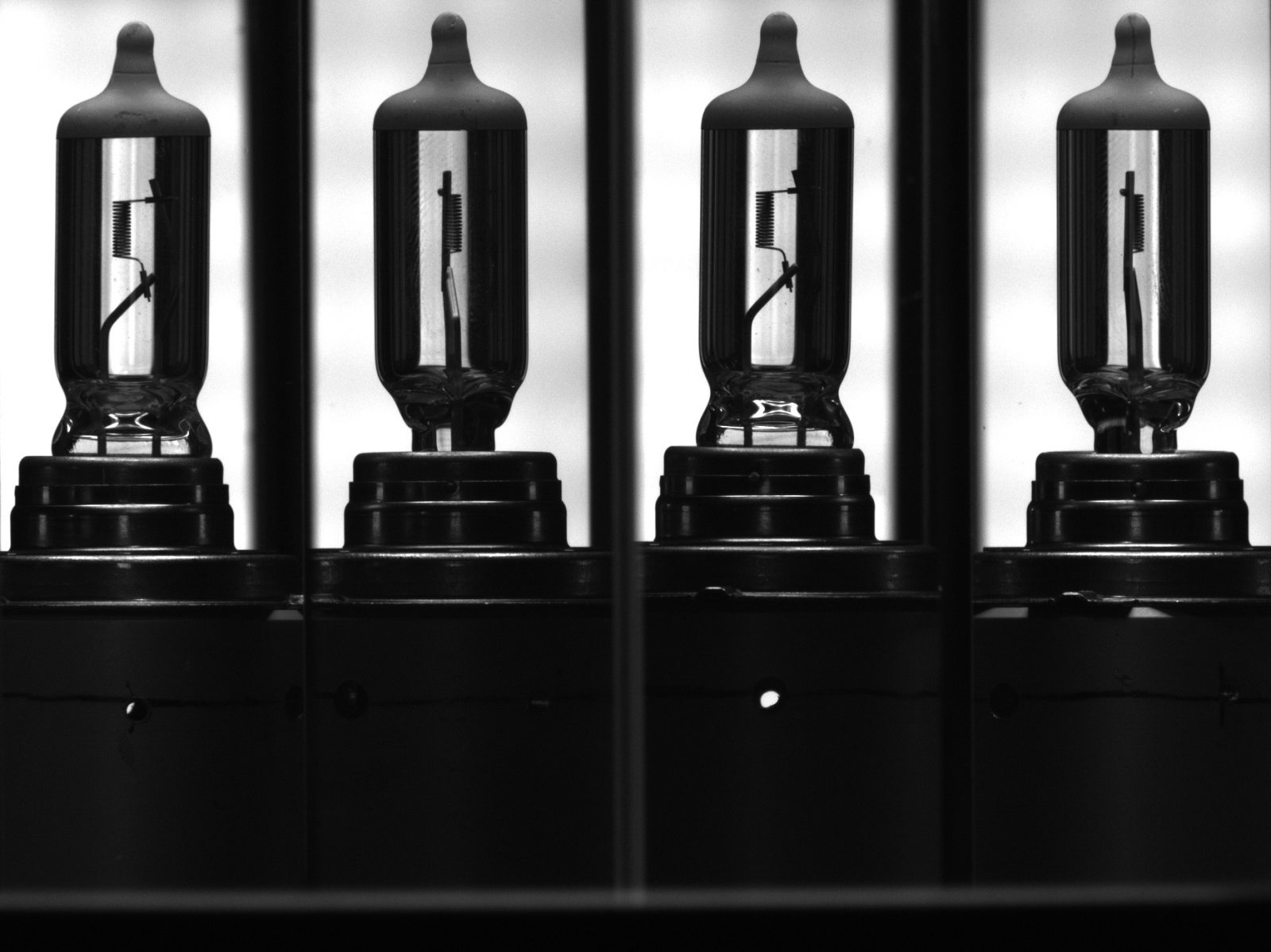
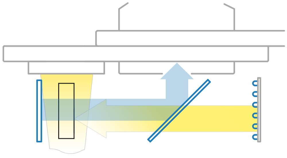
Illumination geometry
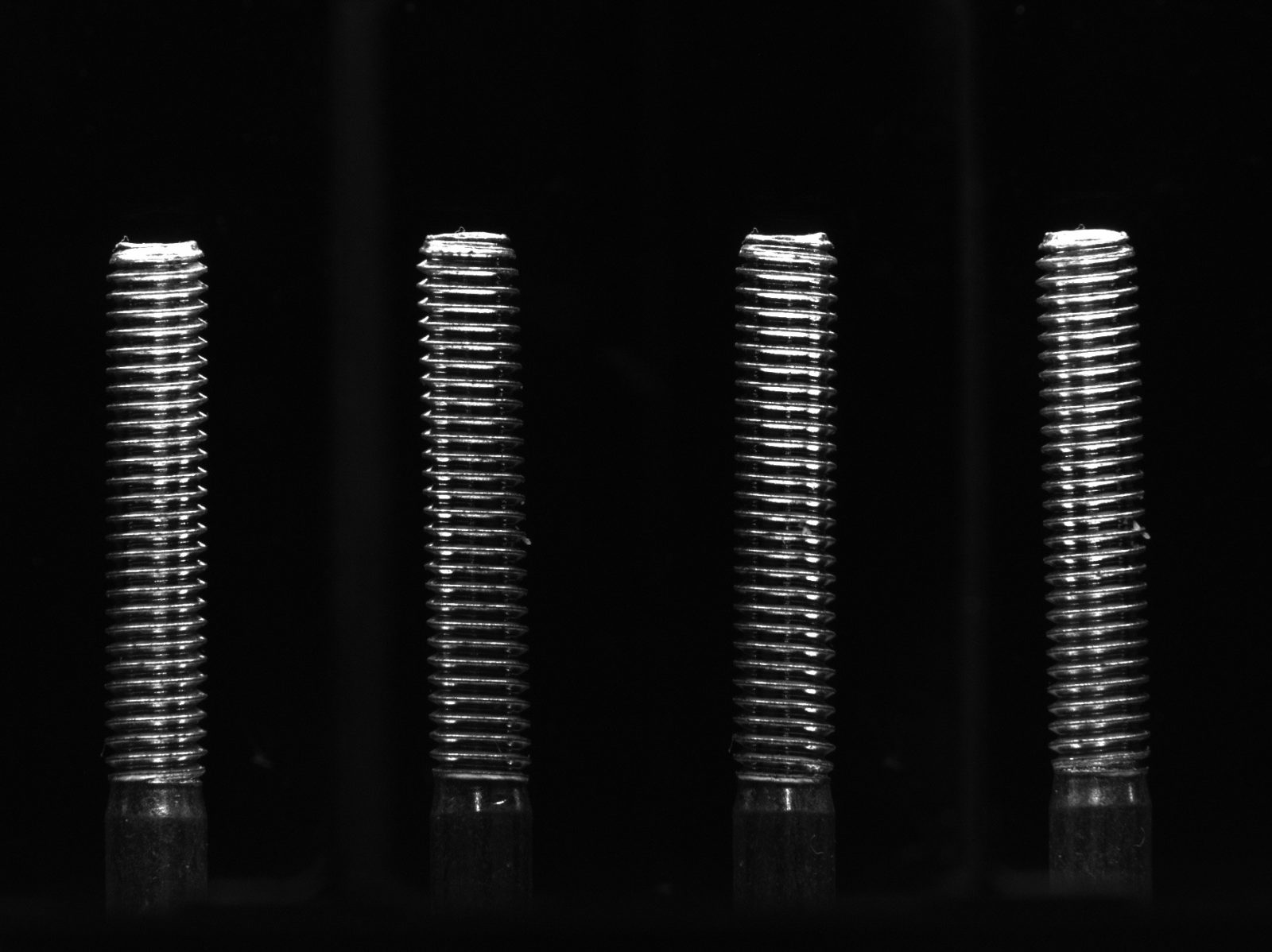
TCCAGE series integrates both direct and backlight illumination. Direct illumination (yellow cone in the drawing) is provided by a ring illuminator placed on the top of the part that can be used to enhance surface defects.
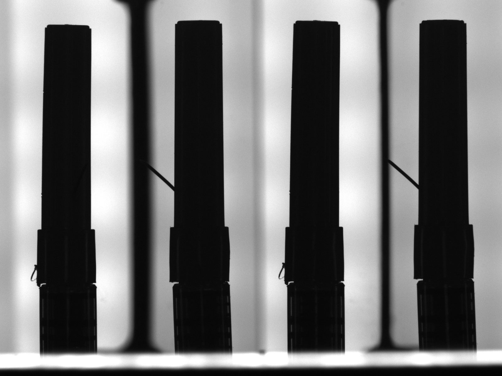
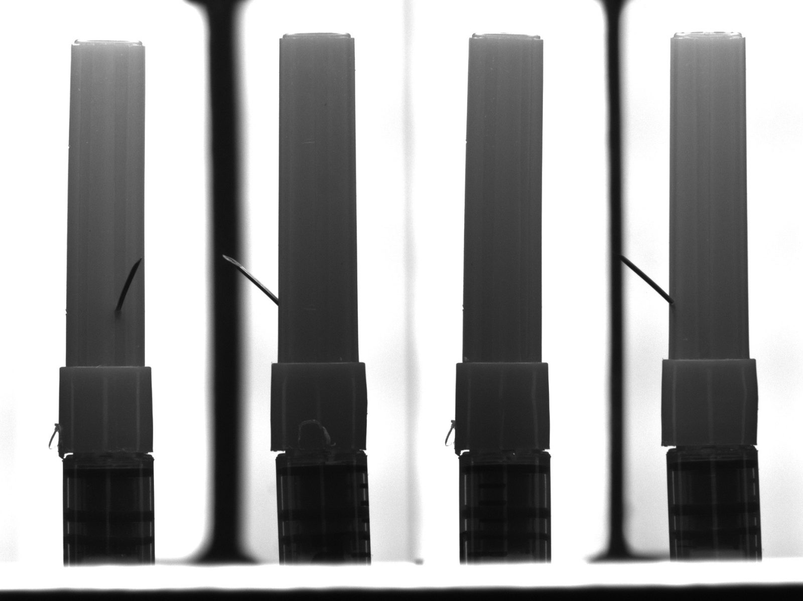
Back lighting (indicated by the yellow arrow) is obtained by means of a diffuse source which illuminates the object through the mirror system; this type of illumination is suggested for measurement purposes or to inspect transparent objects.
Video gallery

Sample applications of TCCAGE imaging
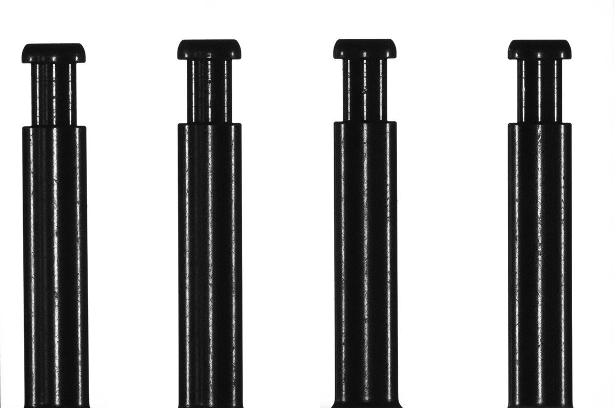
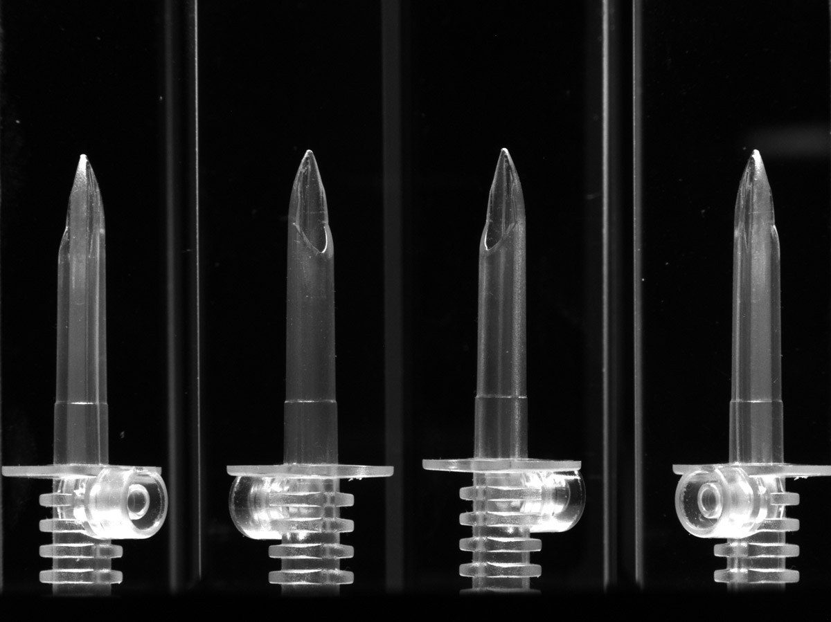
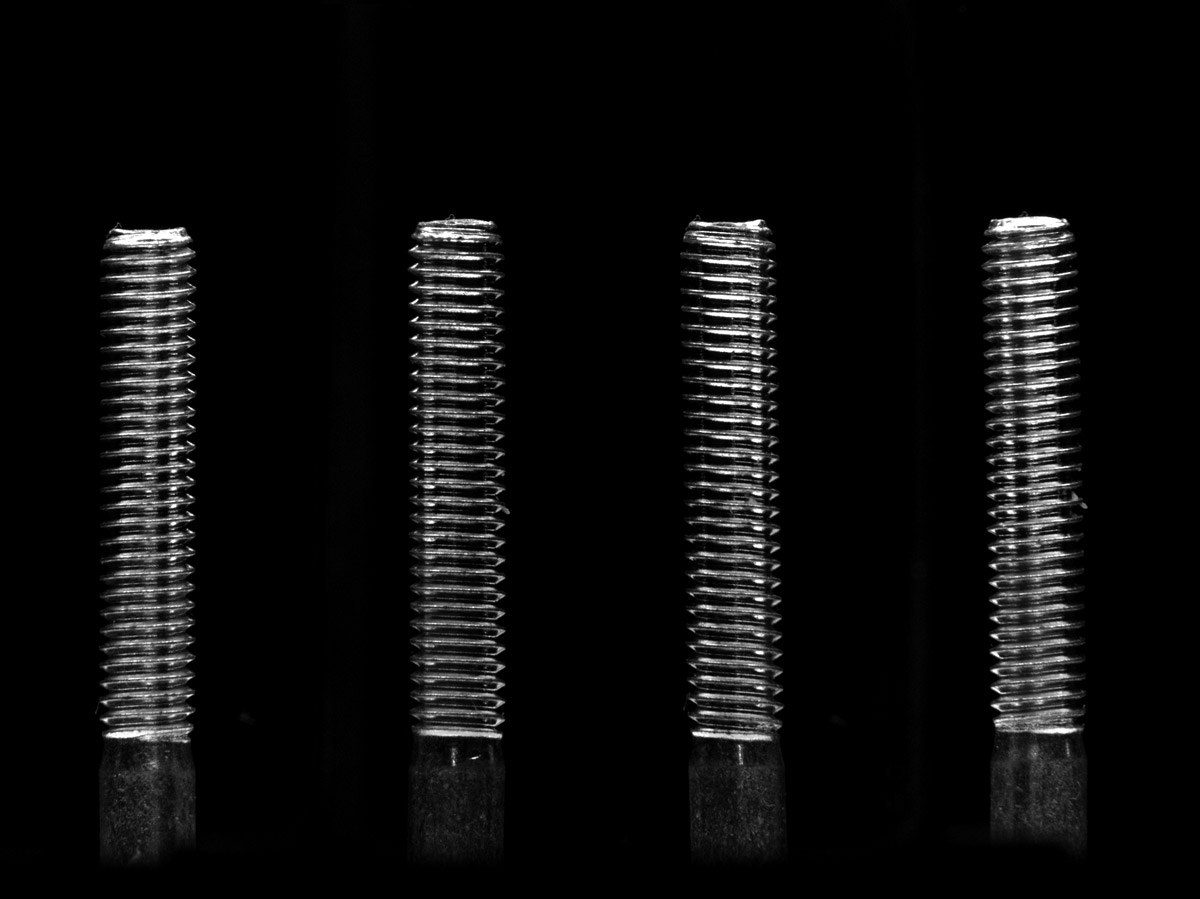
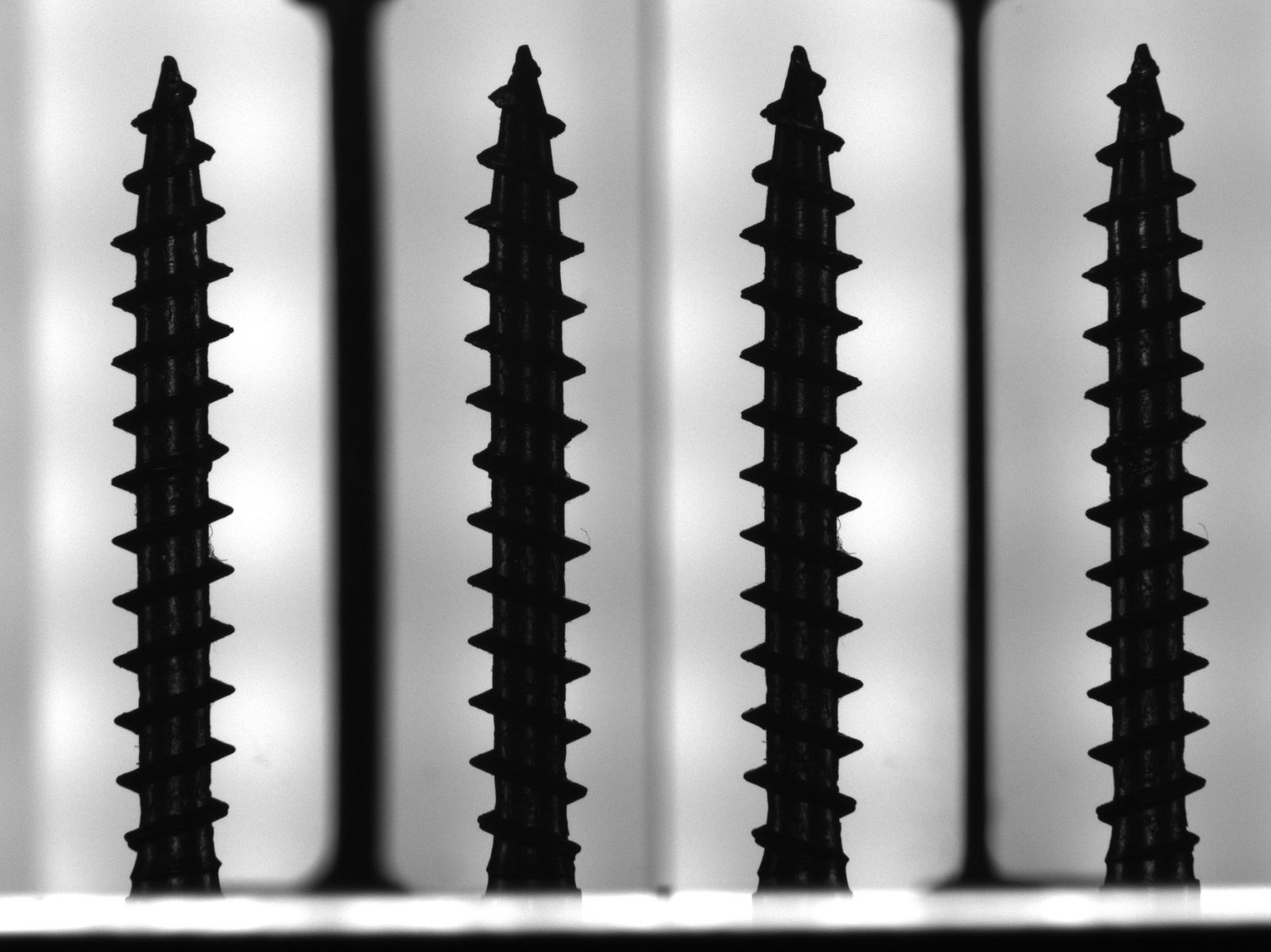
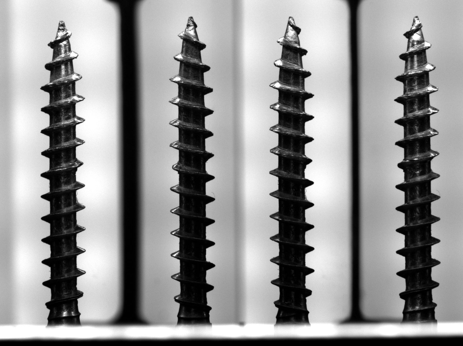
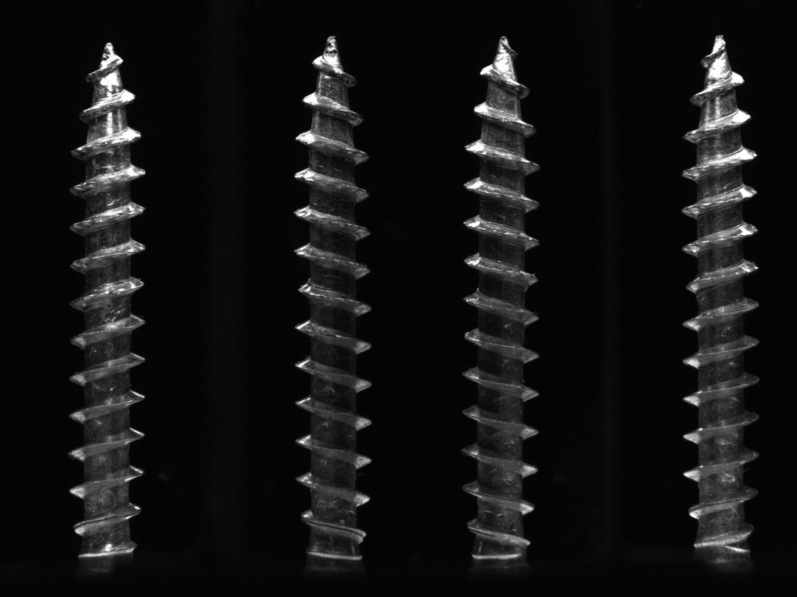
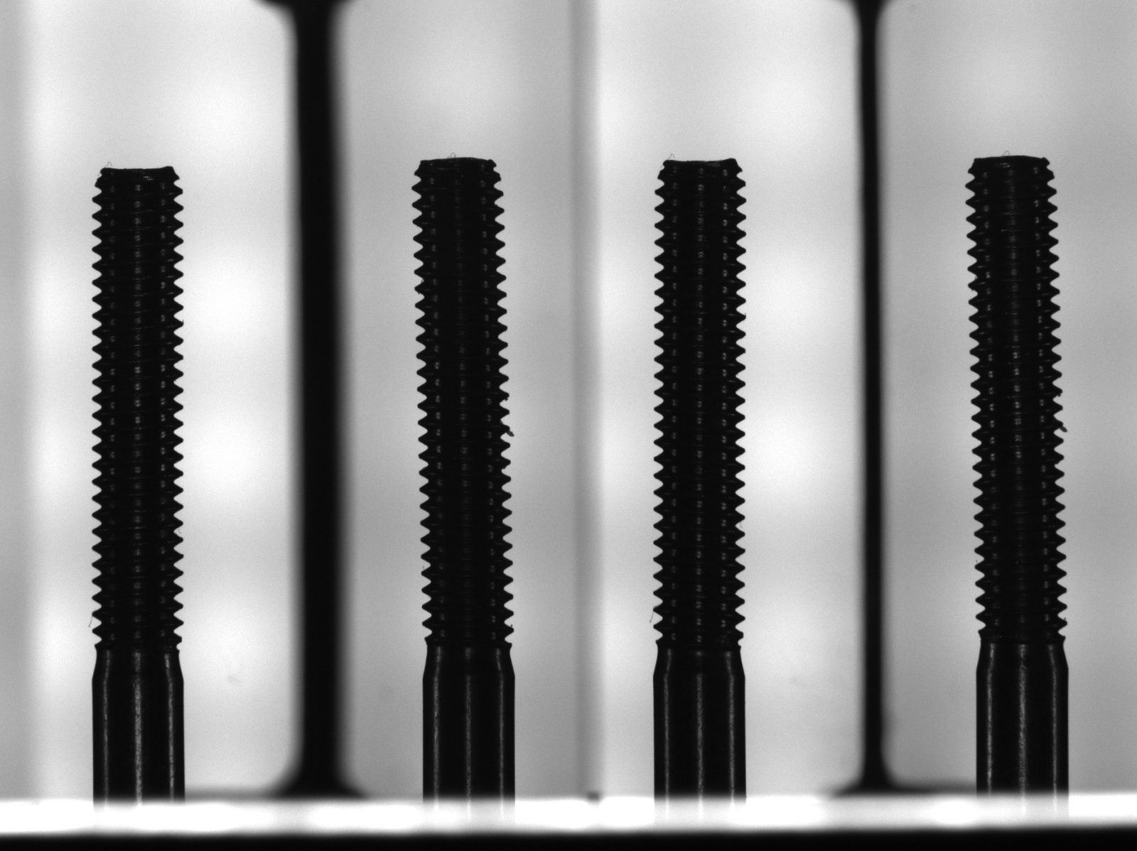
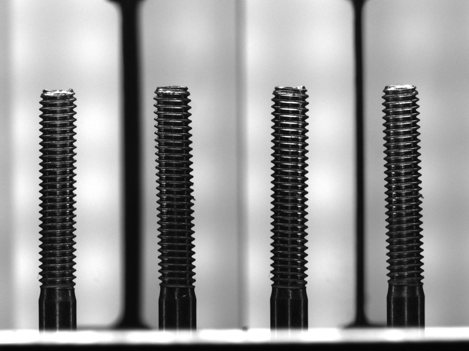
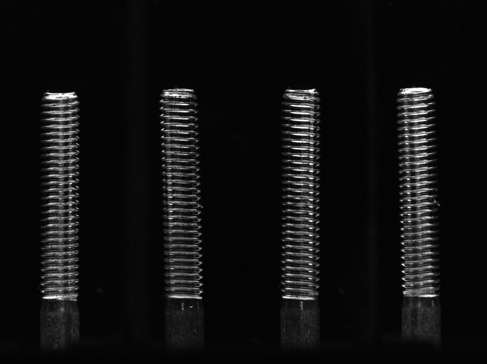
Self-threading screw imaging
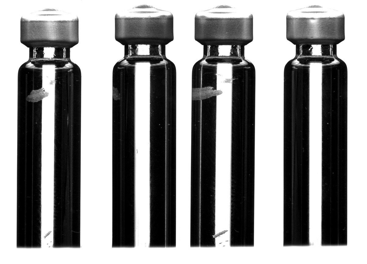
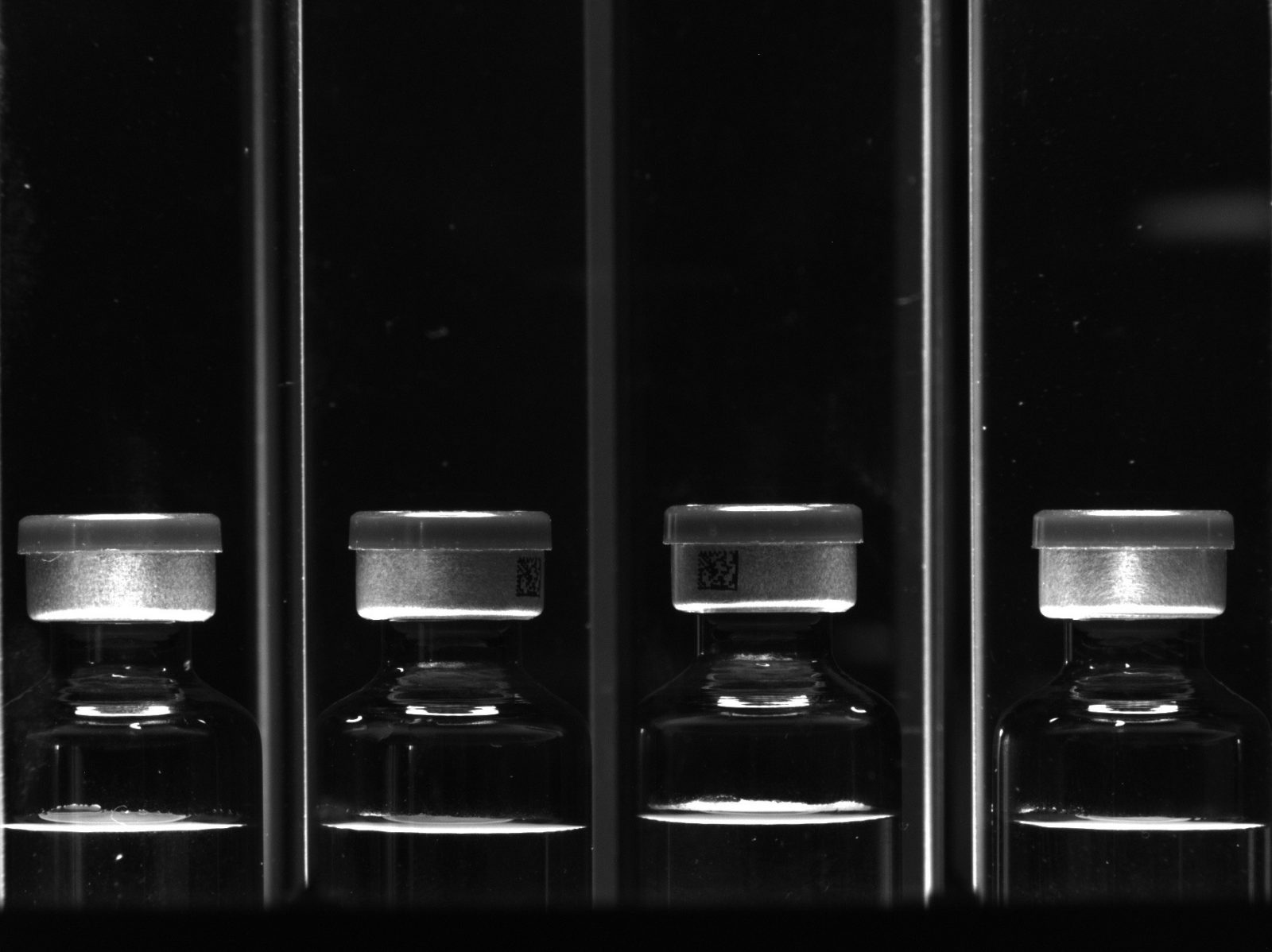
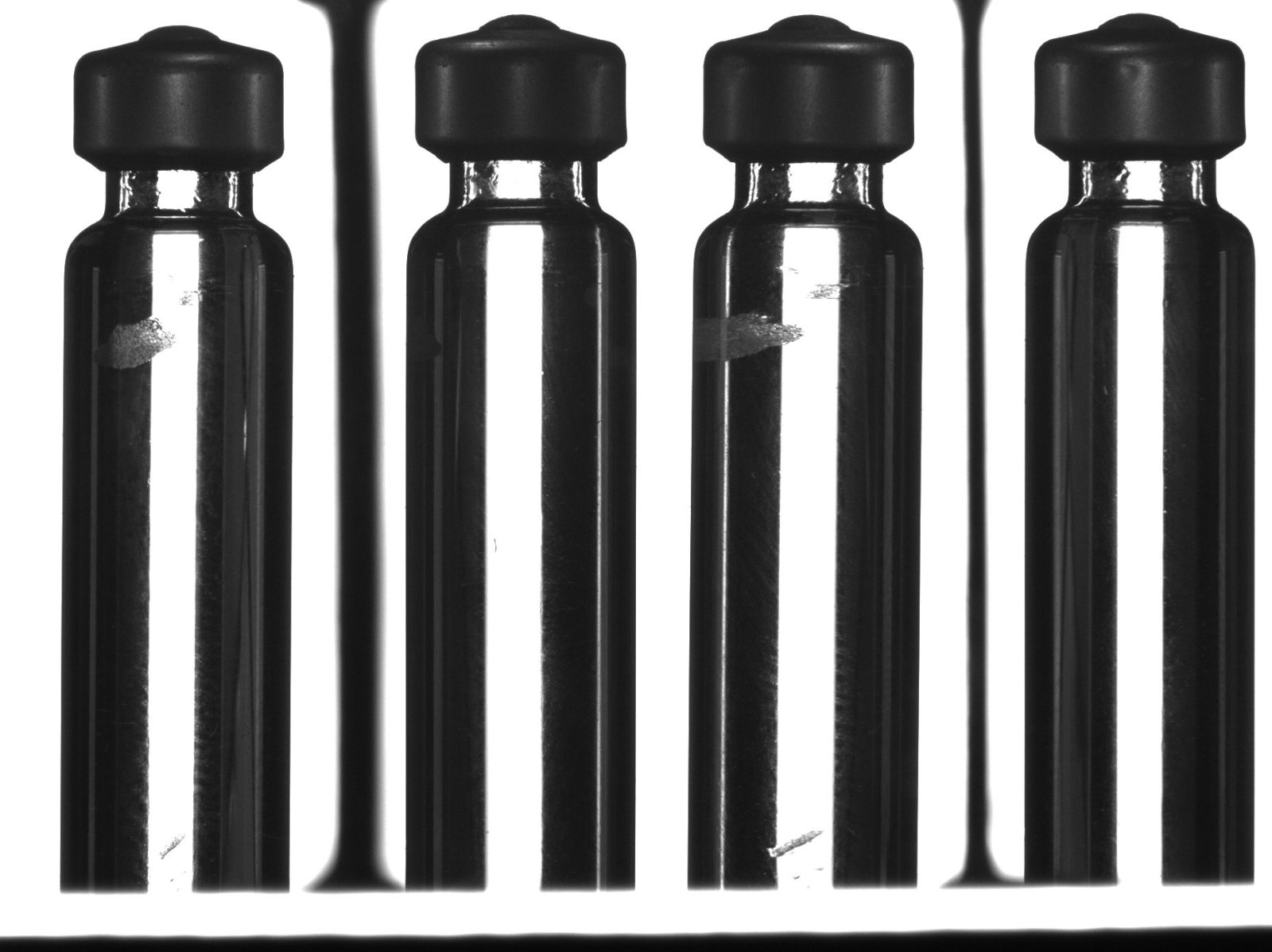
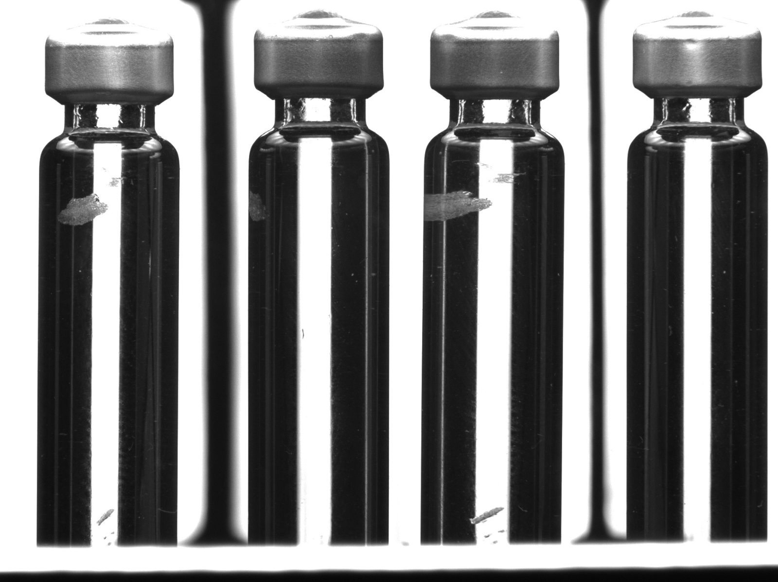
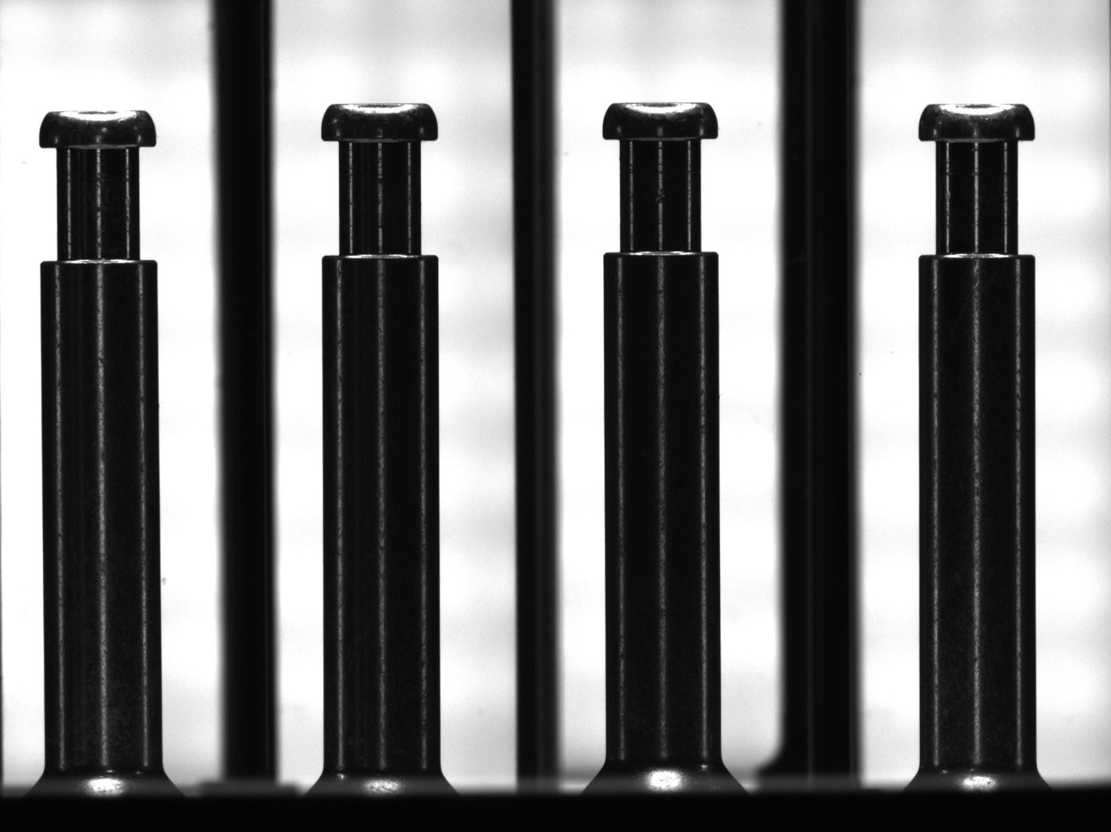
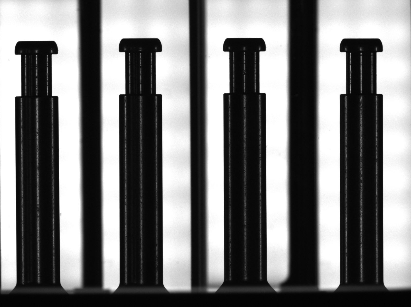
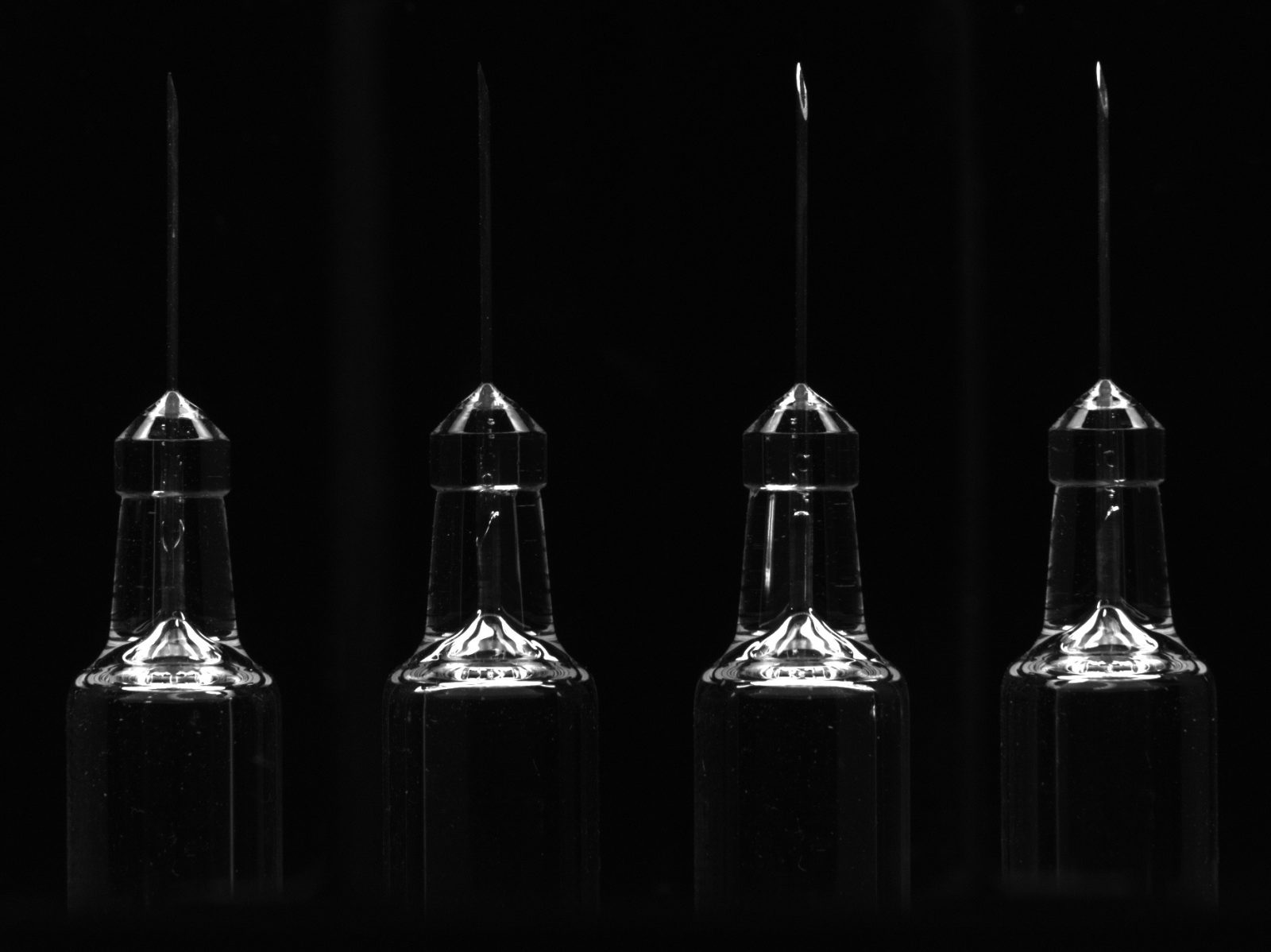
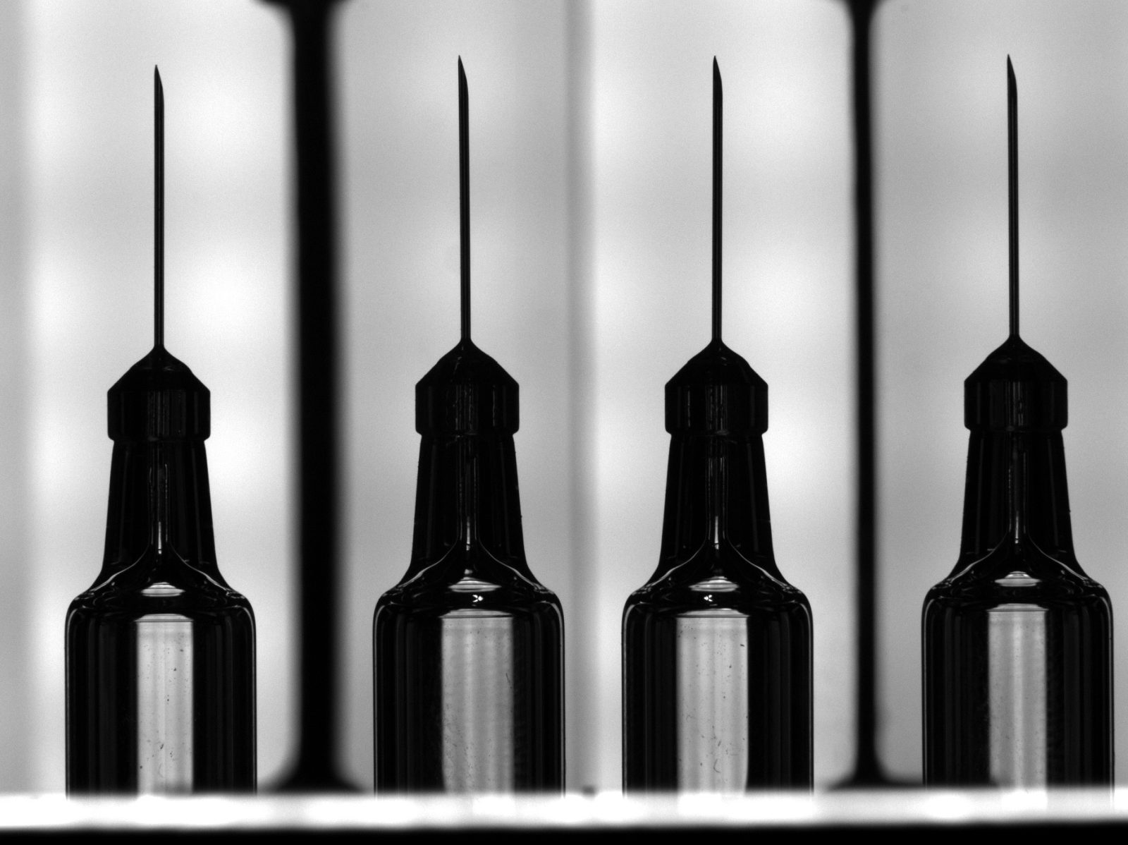
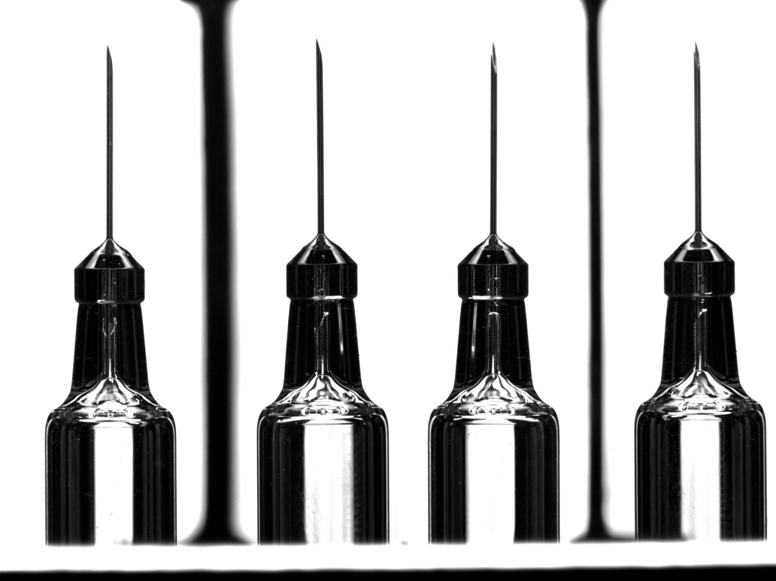
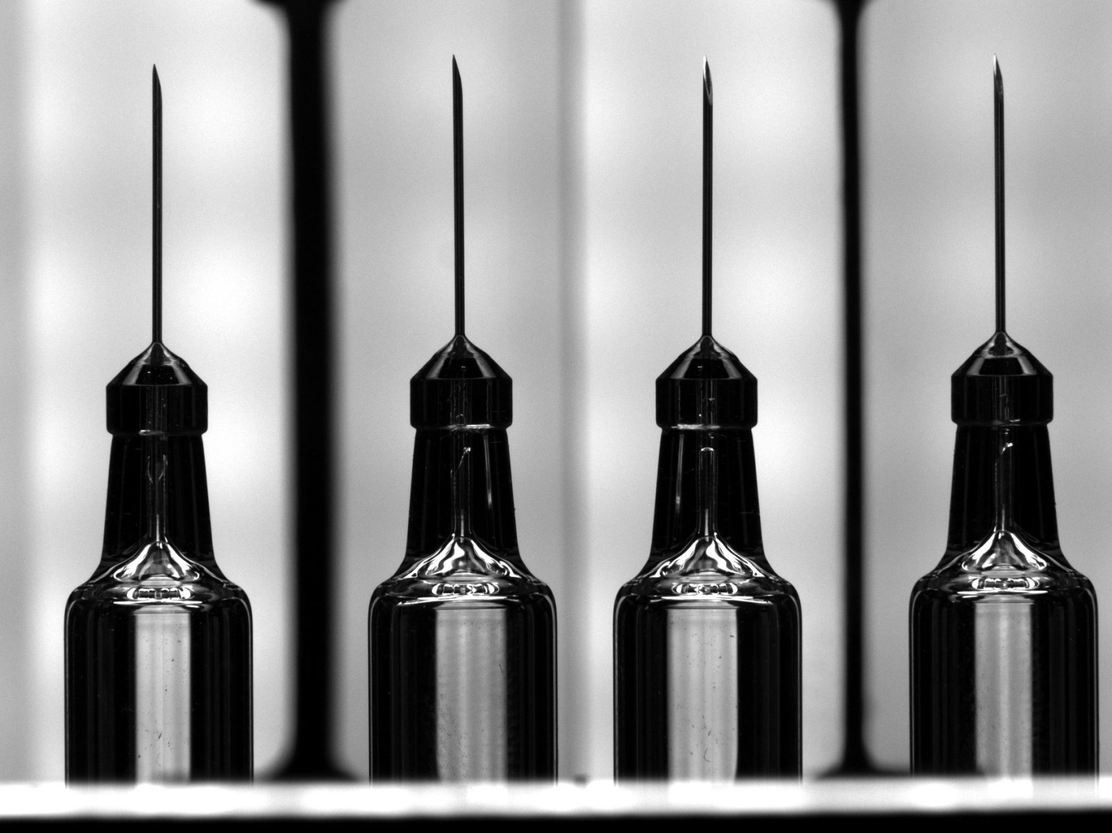
Pharmaceutical component


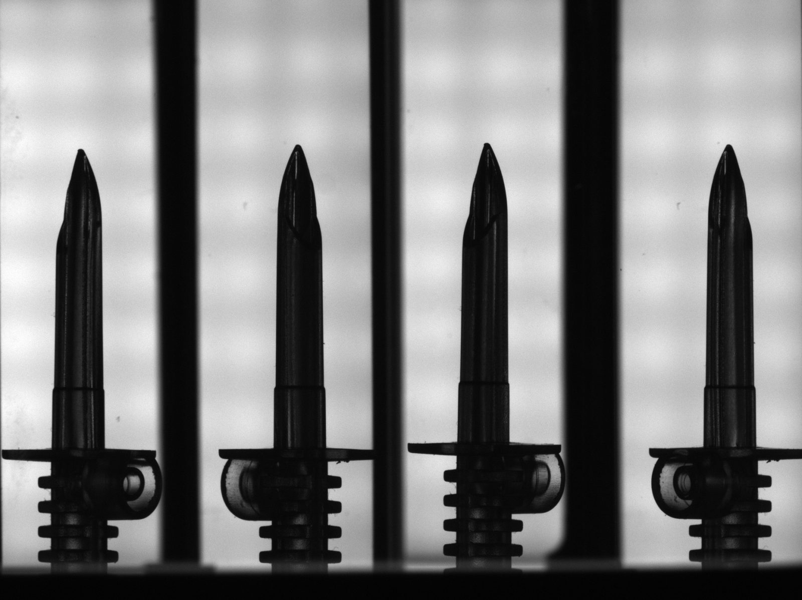
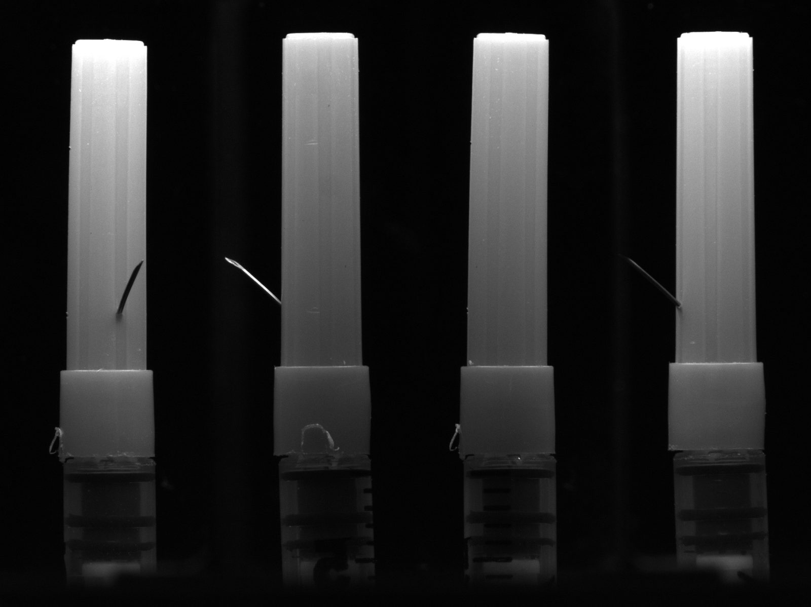
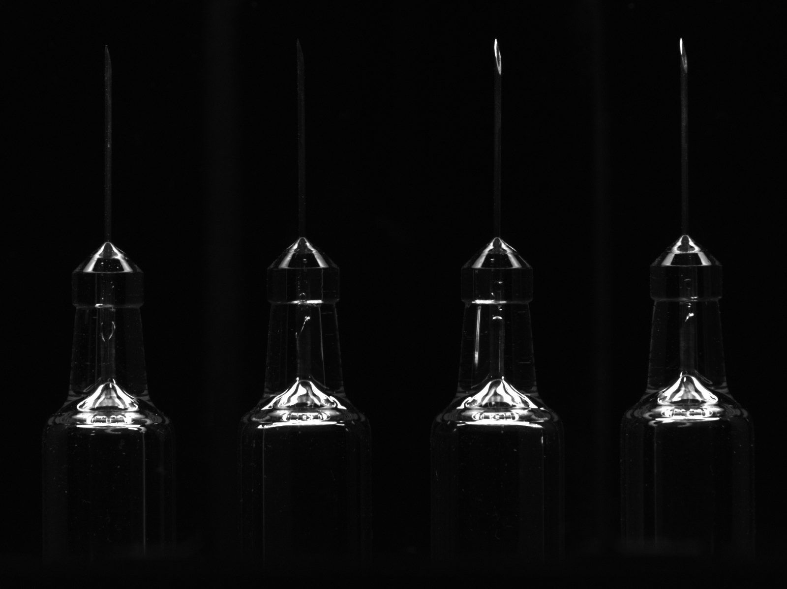
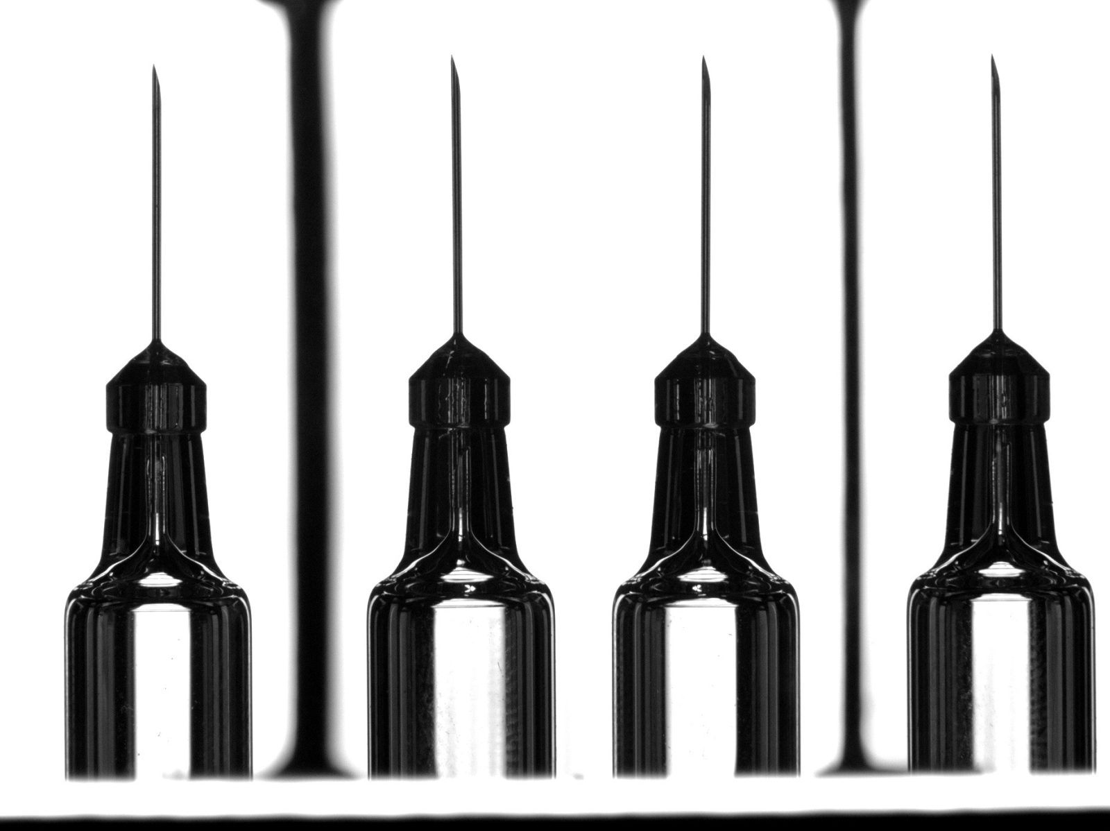
Syringe cap inspection

Mignon bottle imaging
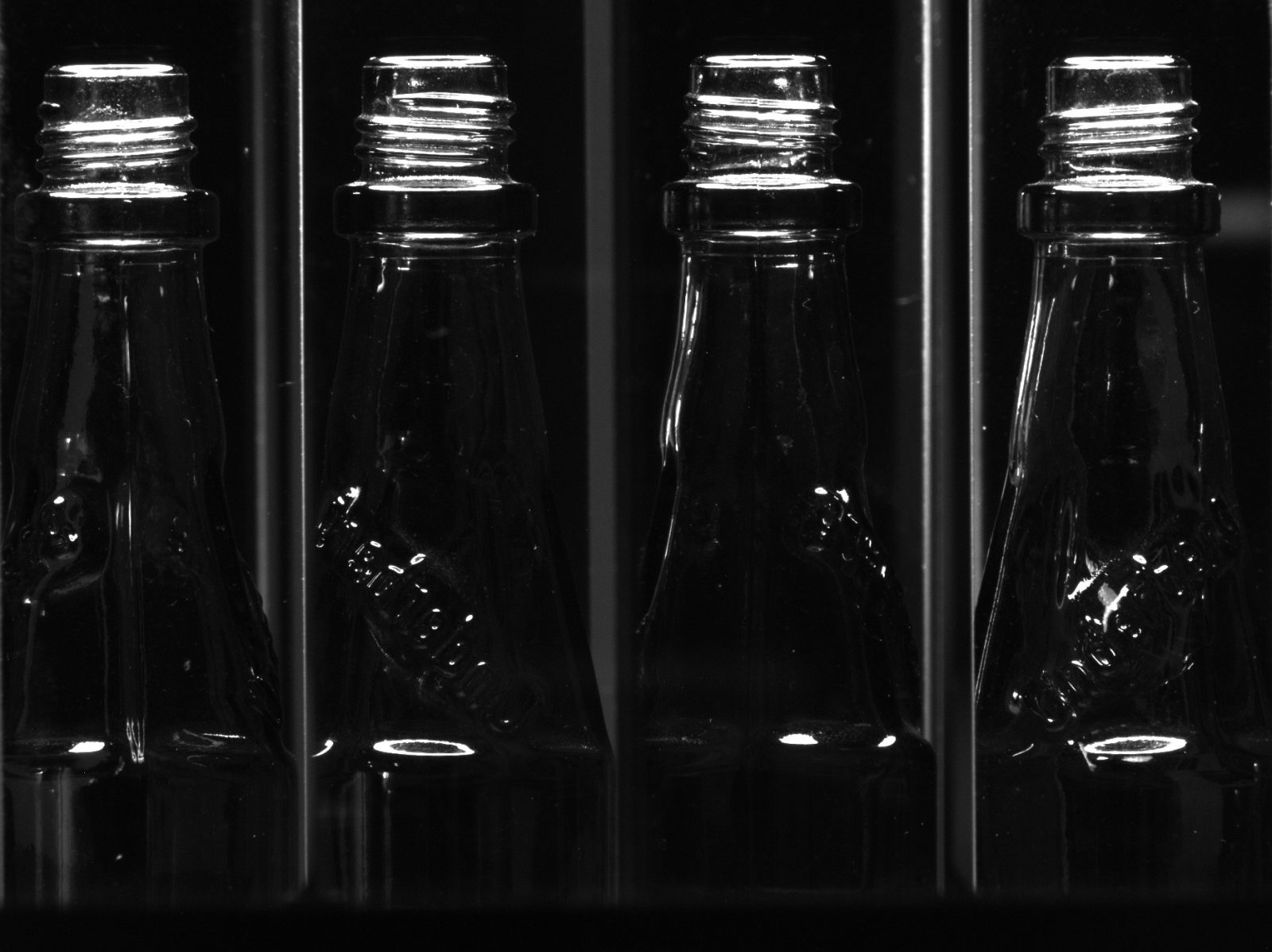
Small pharmaceutical bottle


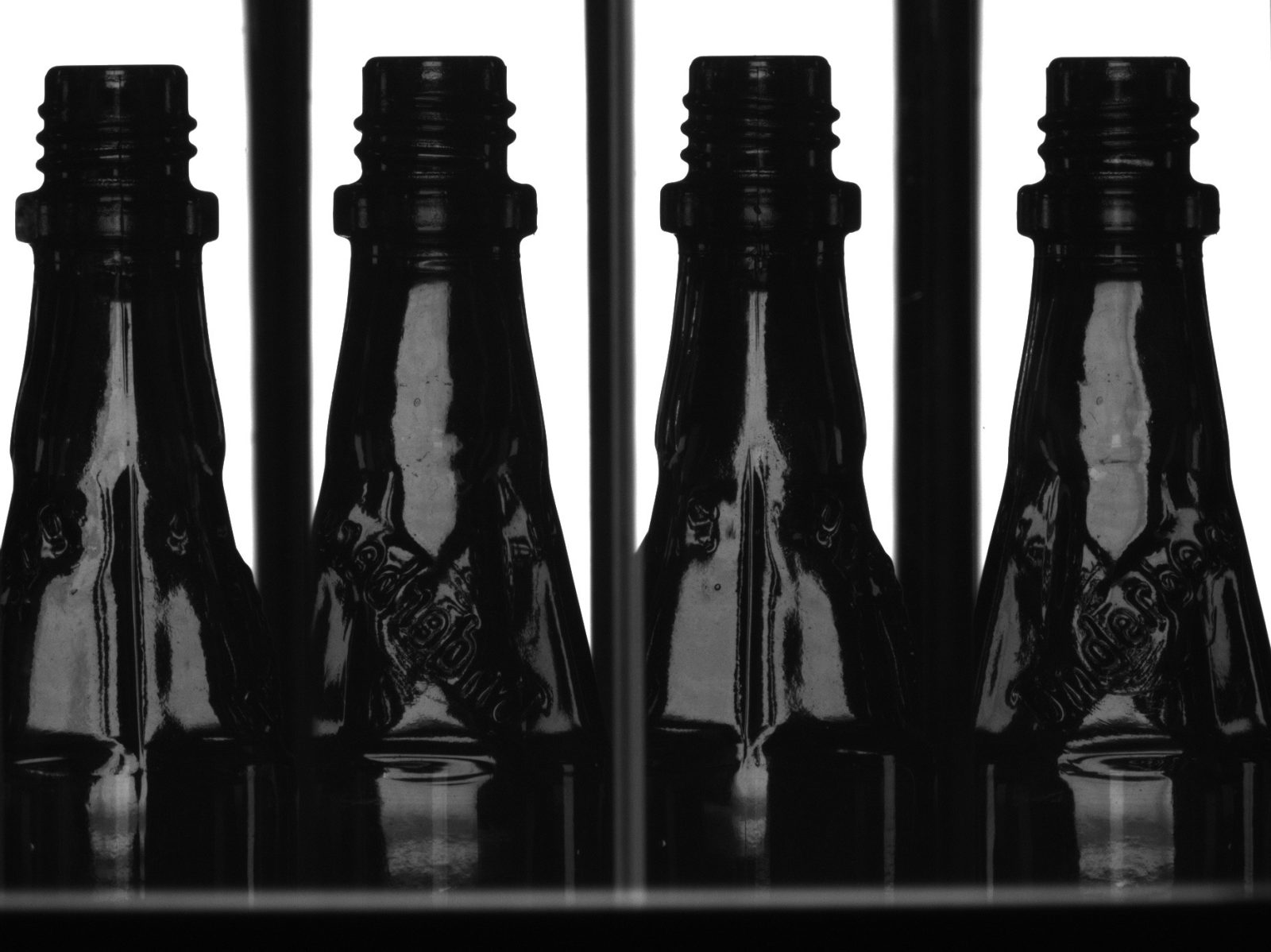
Slim pharmaceutical bottle

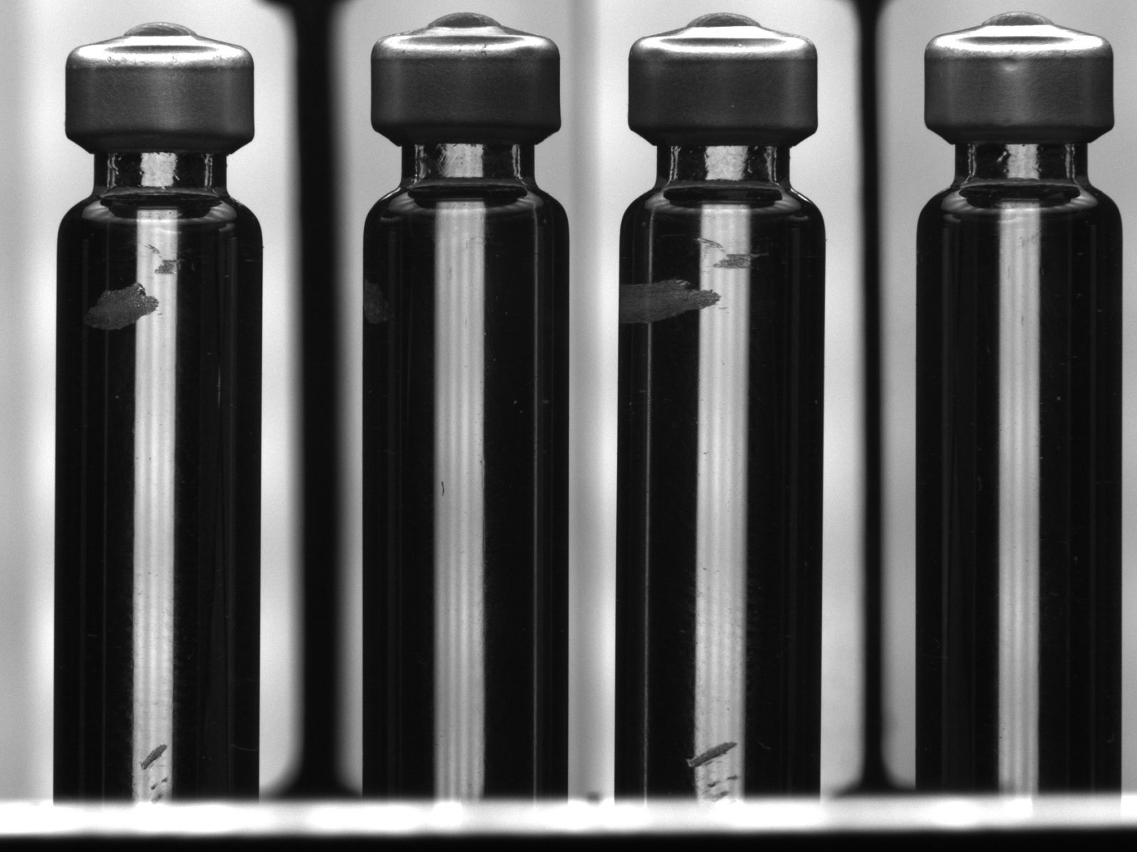
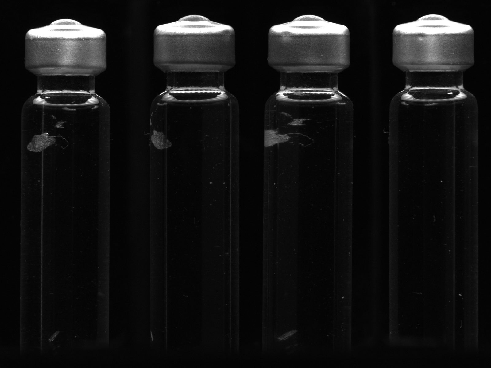
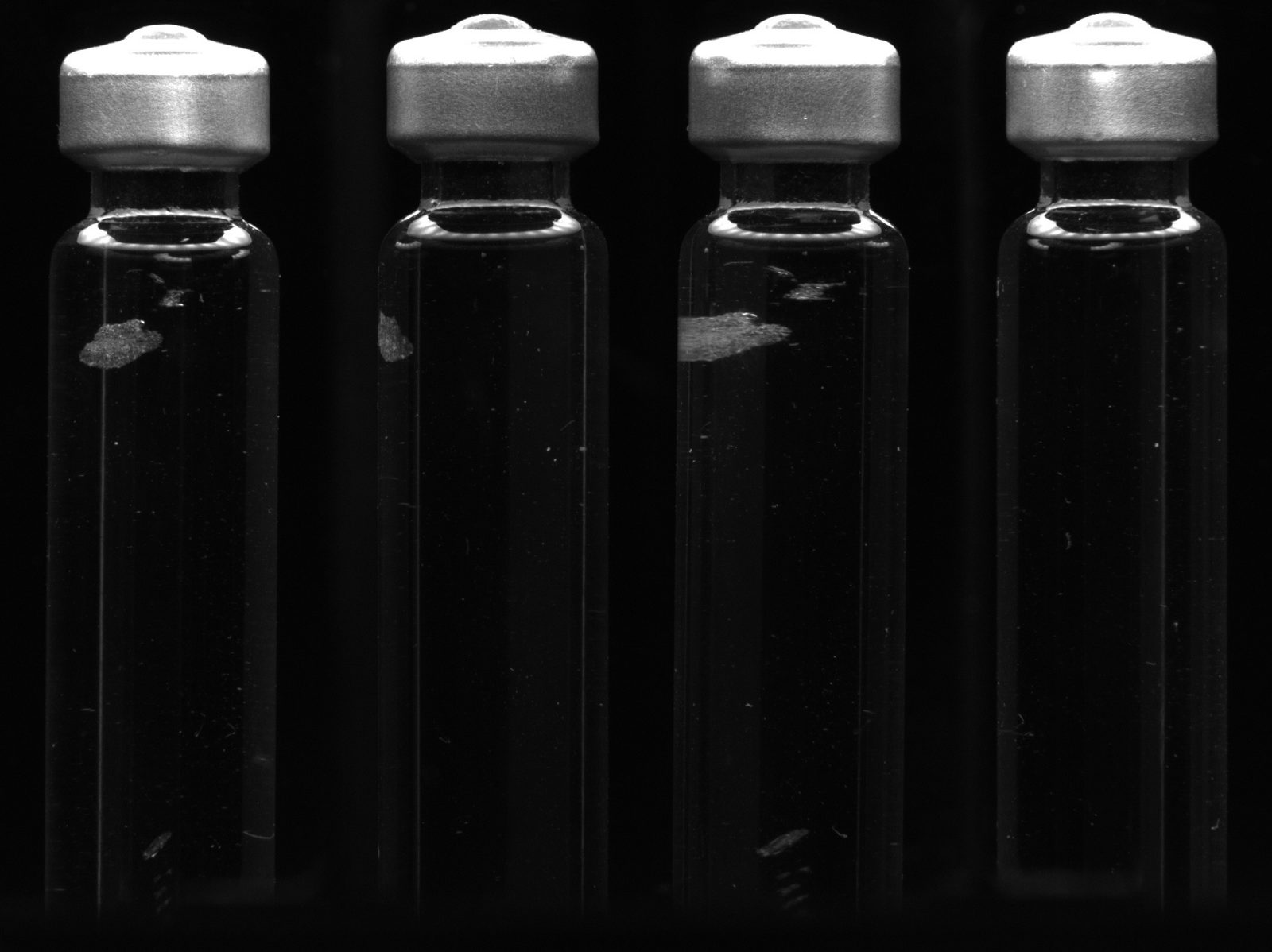
Standard pharmaceutical bottle


M4 screw inspection
Mechanical shaft inspection
Syringe
Automotive lightbulb component