PCPW series
Polyview optics for multiple side views in one image

Key advantages
- Just one camera
No need for multiple cameras placed around and over the object - Wide angle of view
The 45° object sides view makes otherwise hidden features visible - Complete surface inspection
Both inner and outer object surfaces can be imaged in one shot - Very high resolution
Even the tiniest defects can be detected.
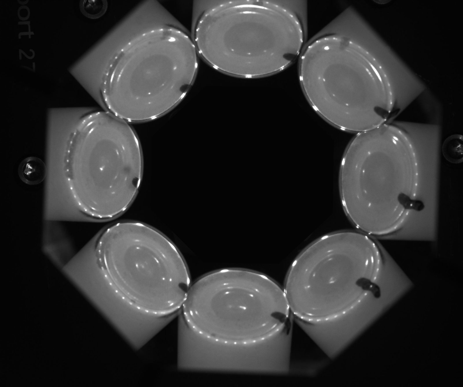
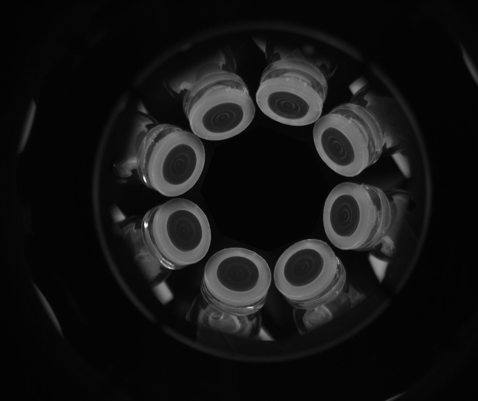
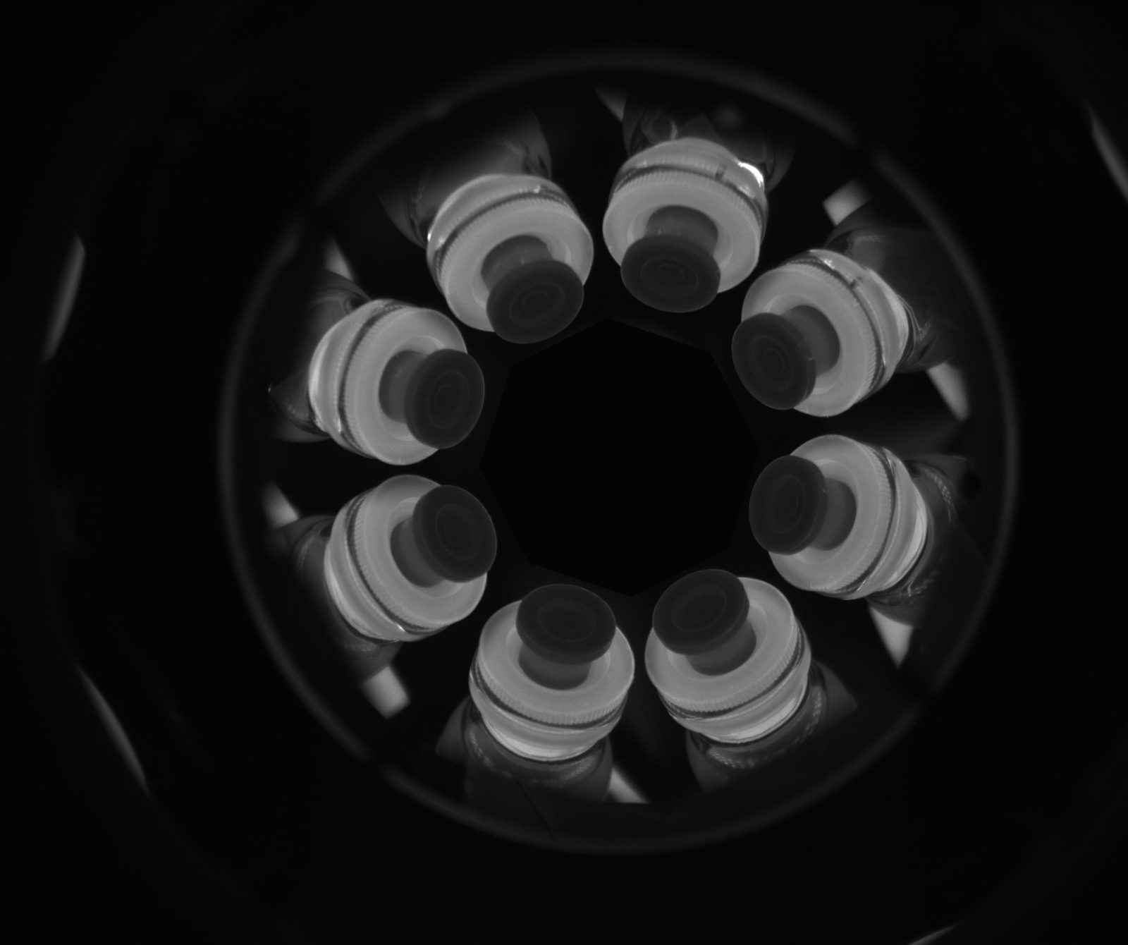
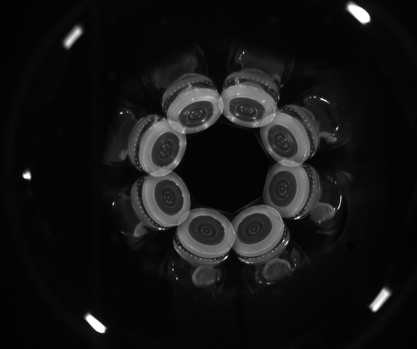
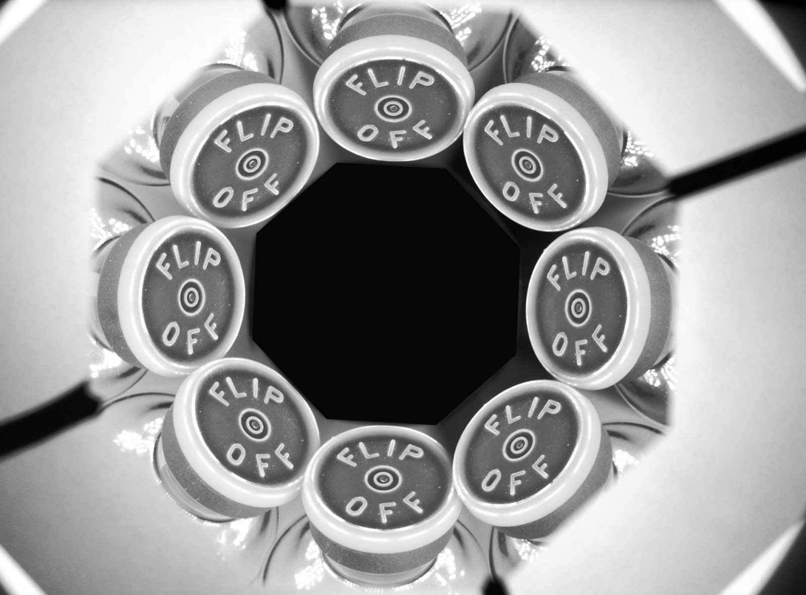
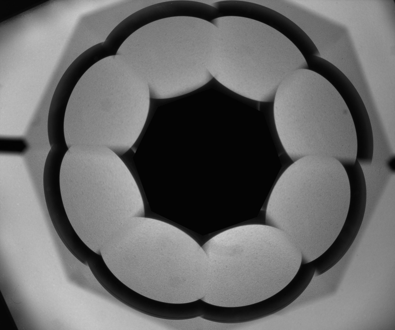
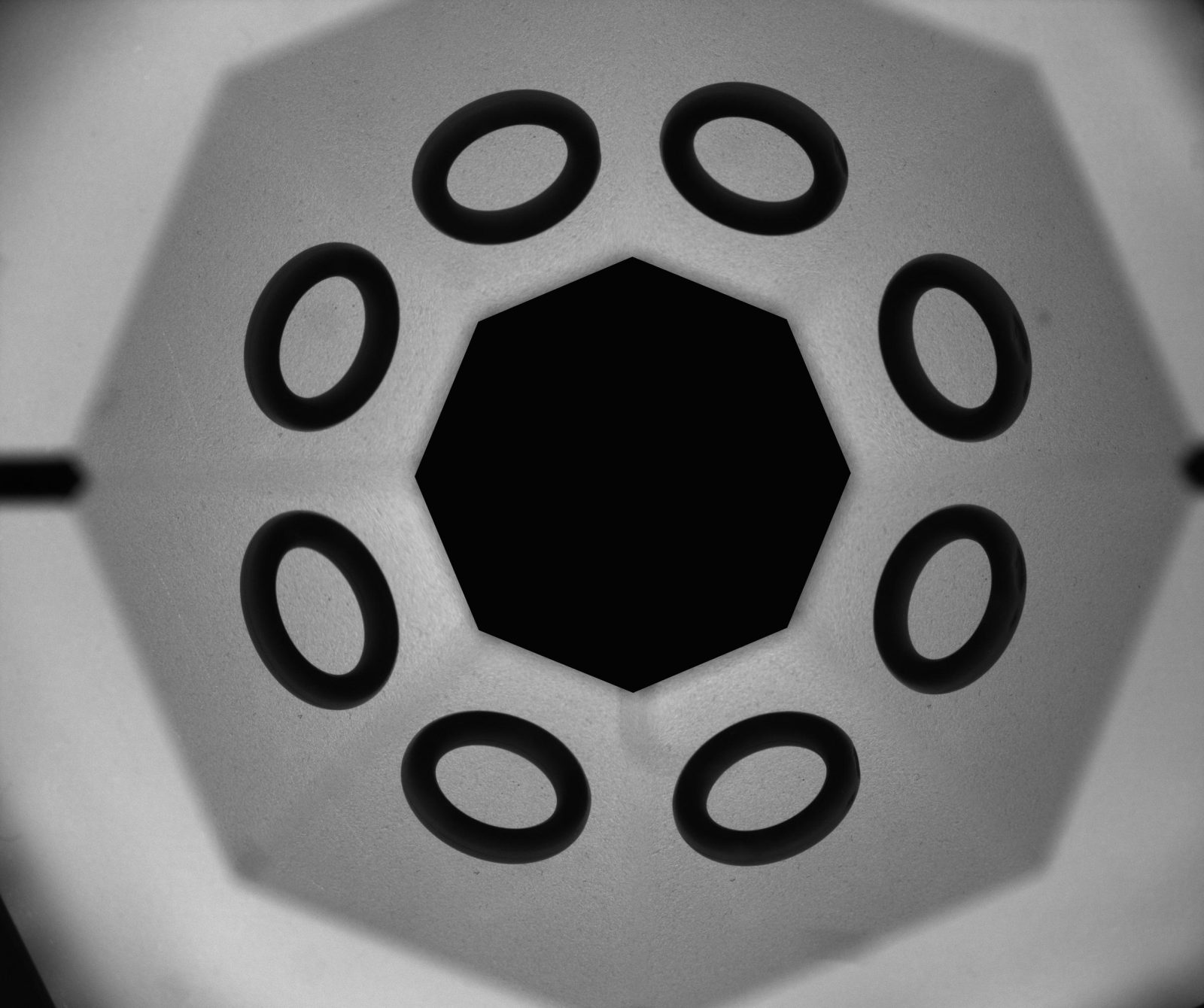
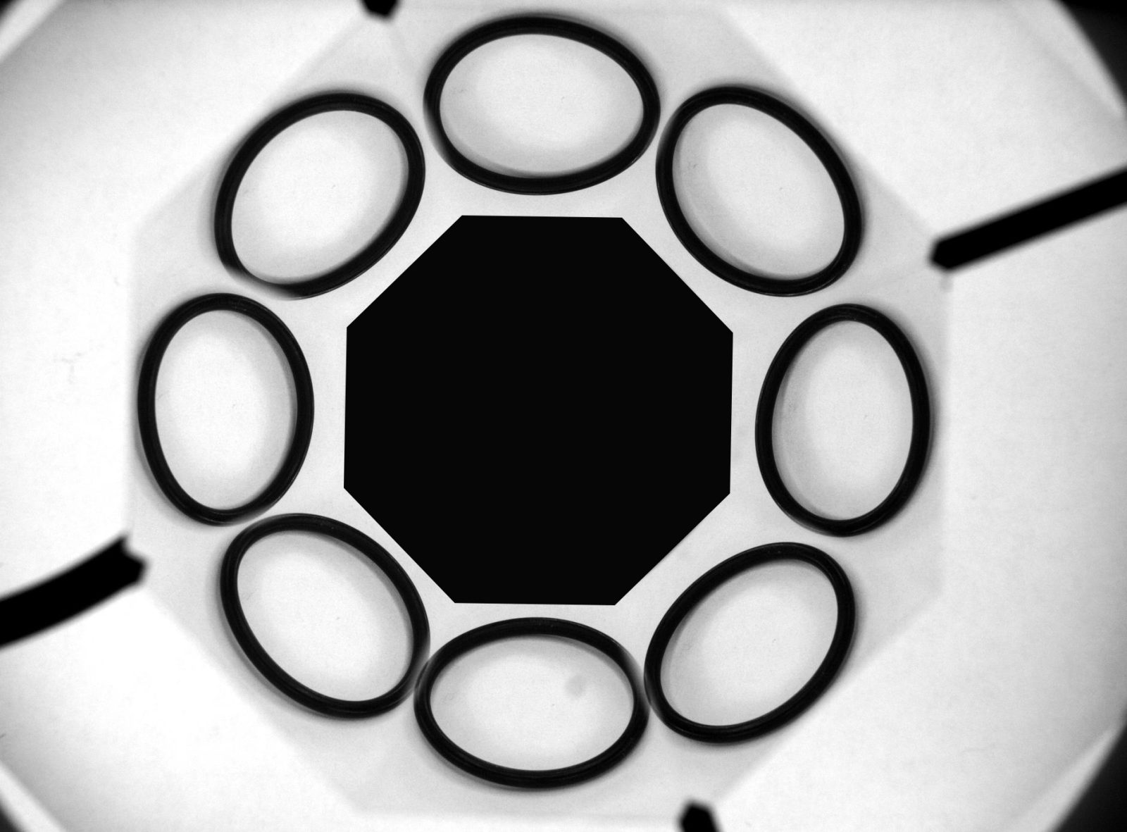
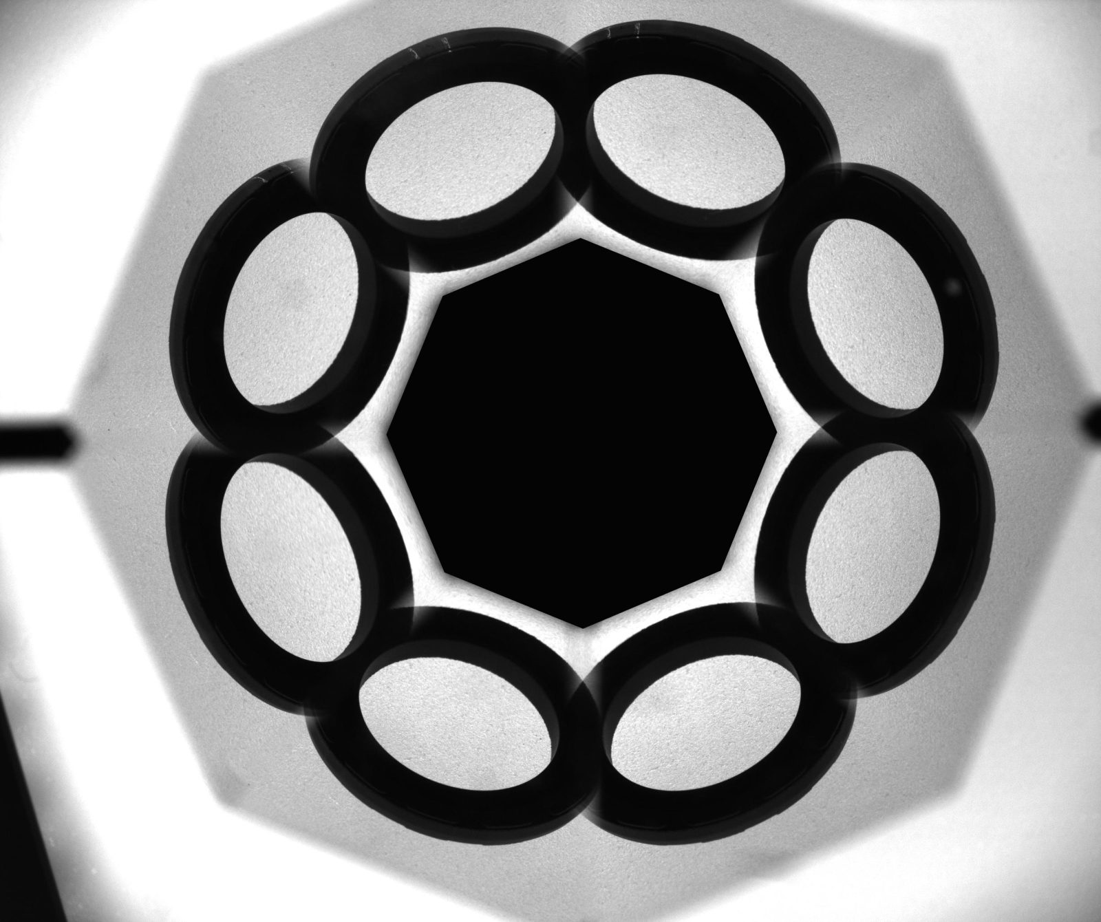
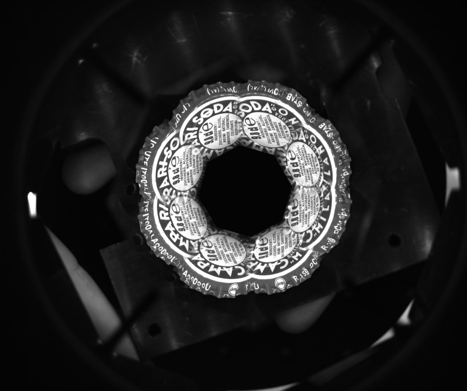
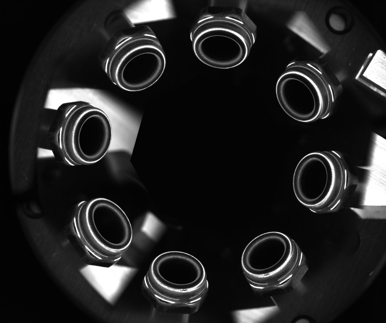
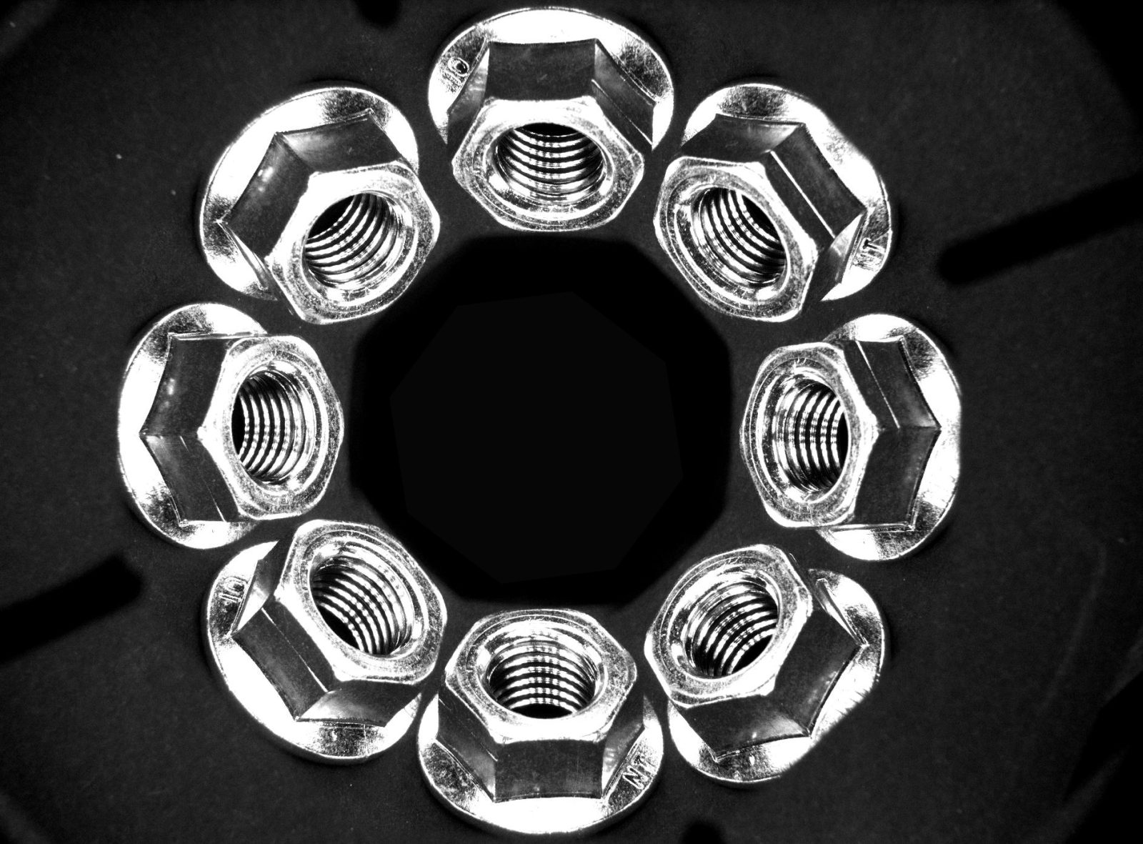
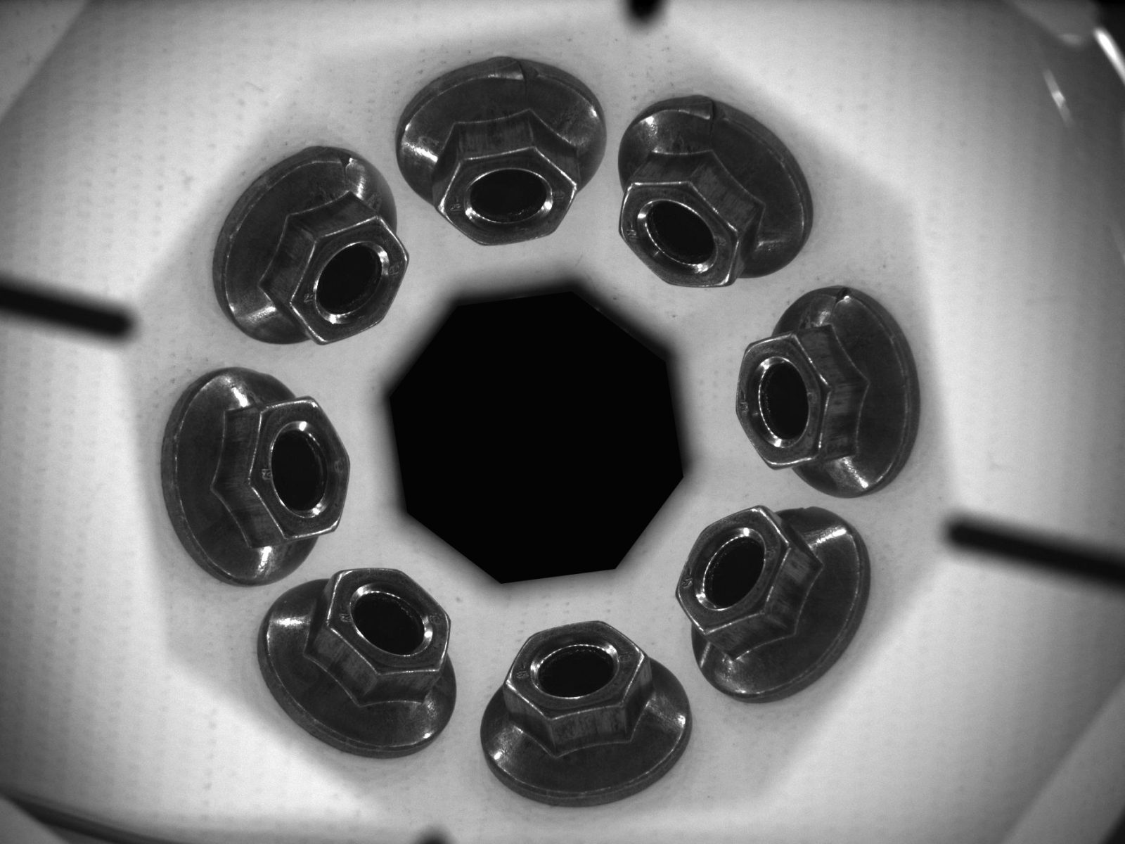
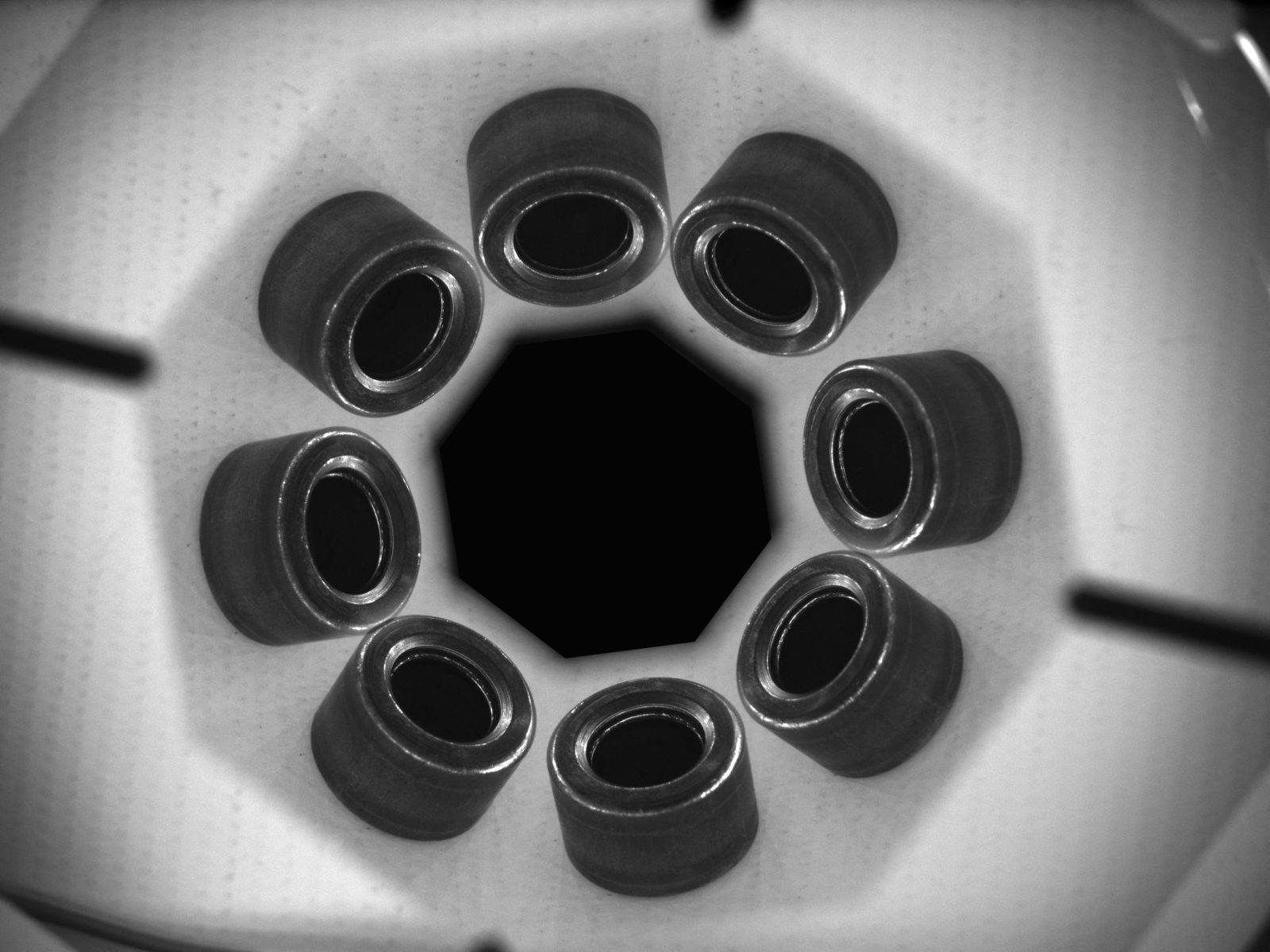
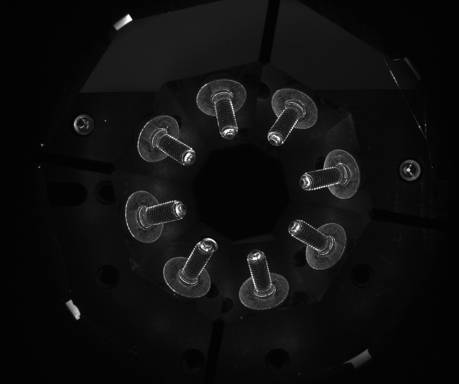
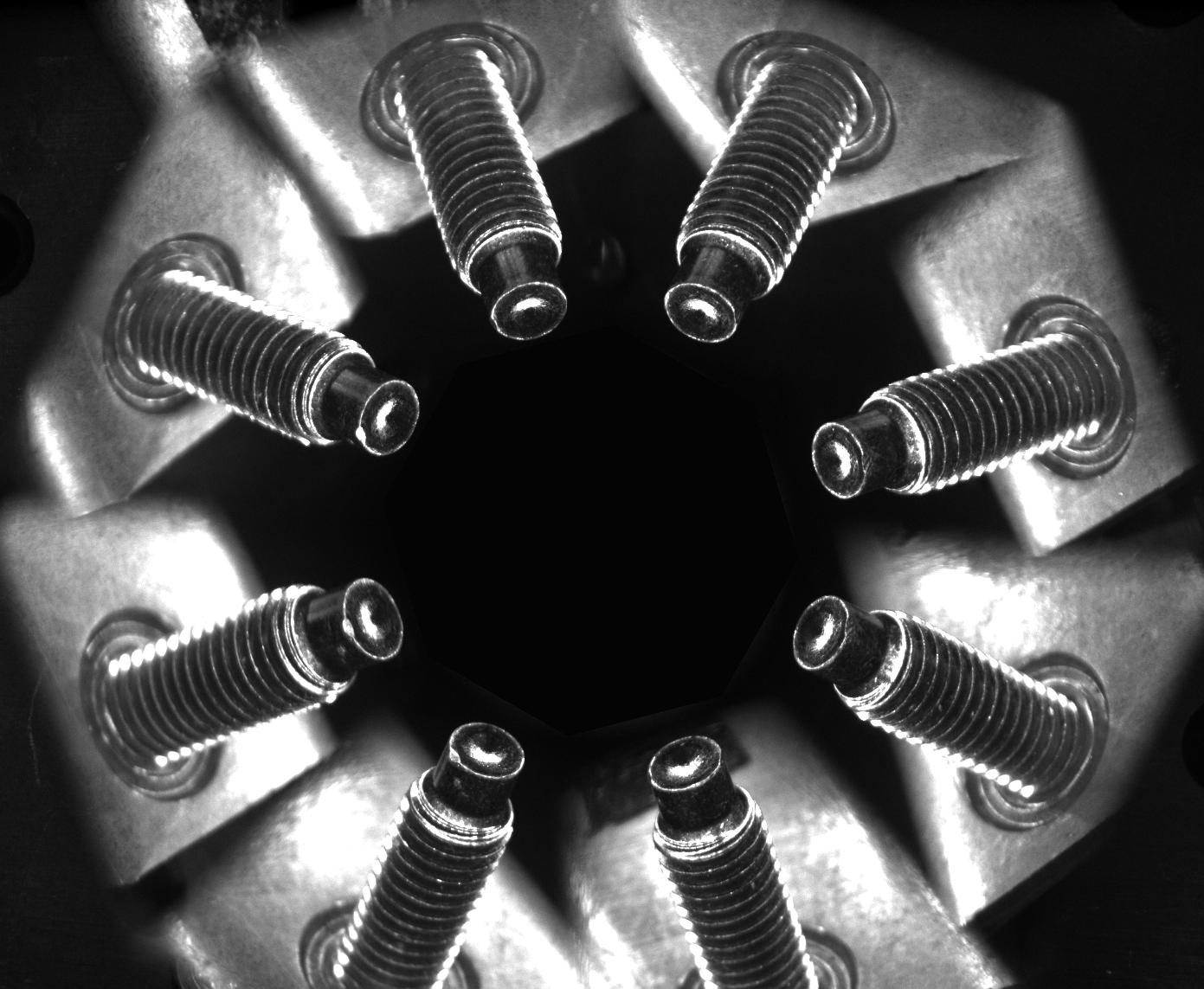
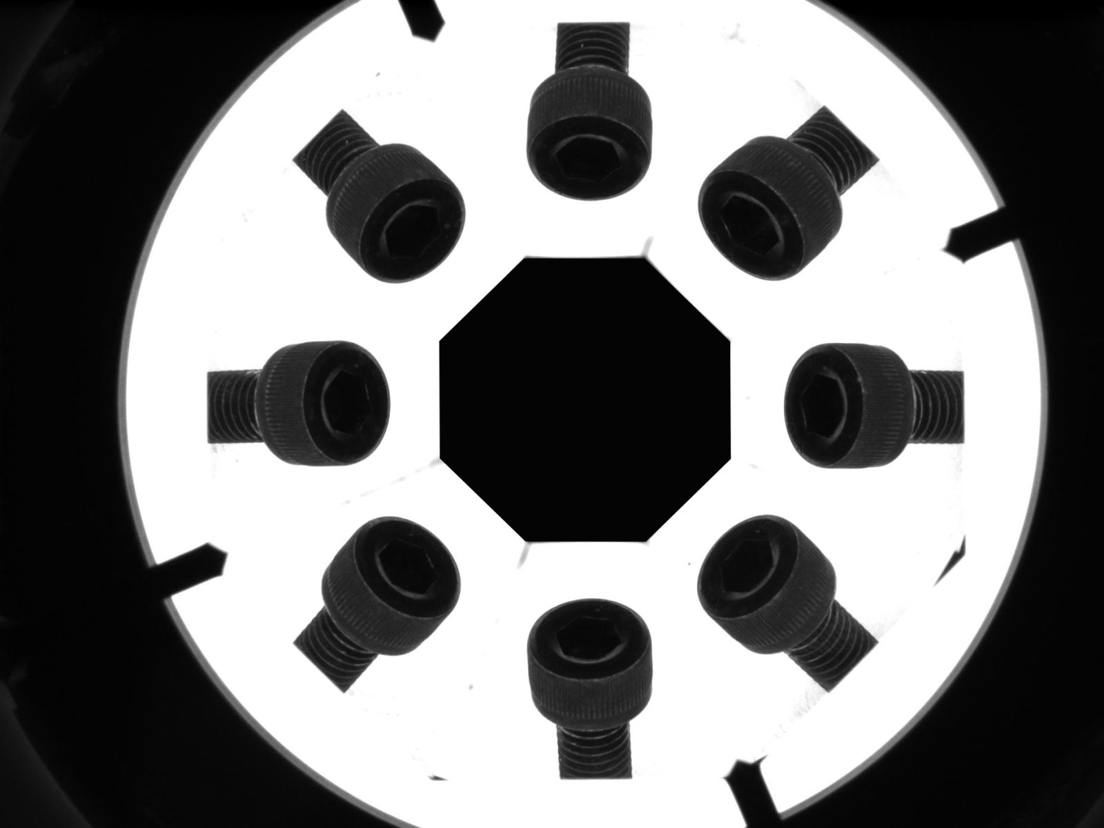
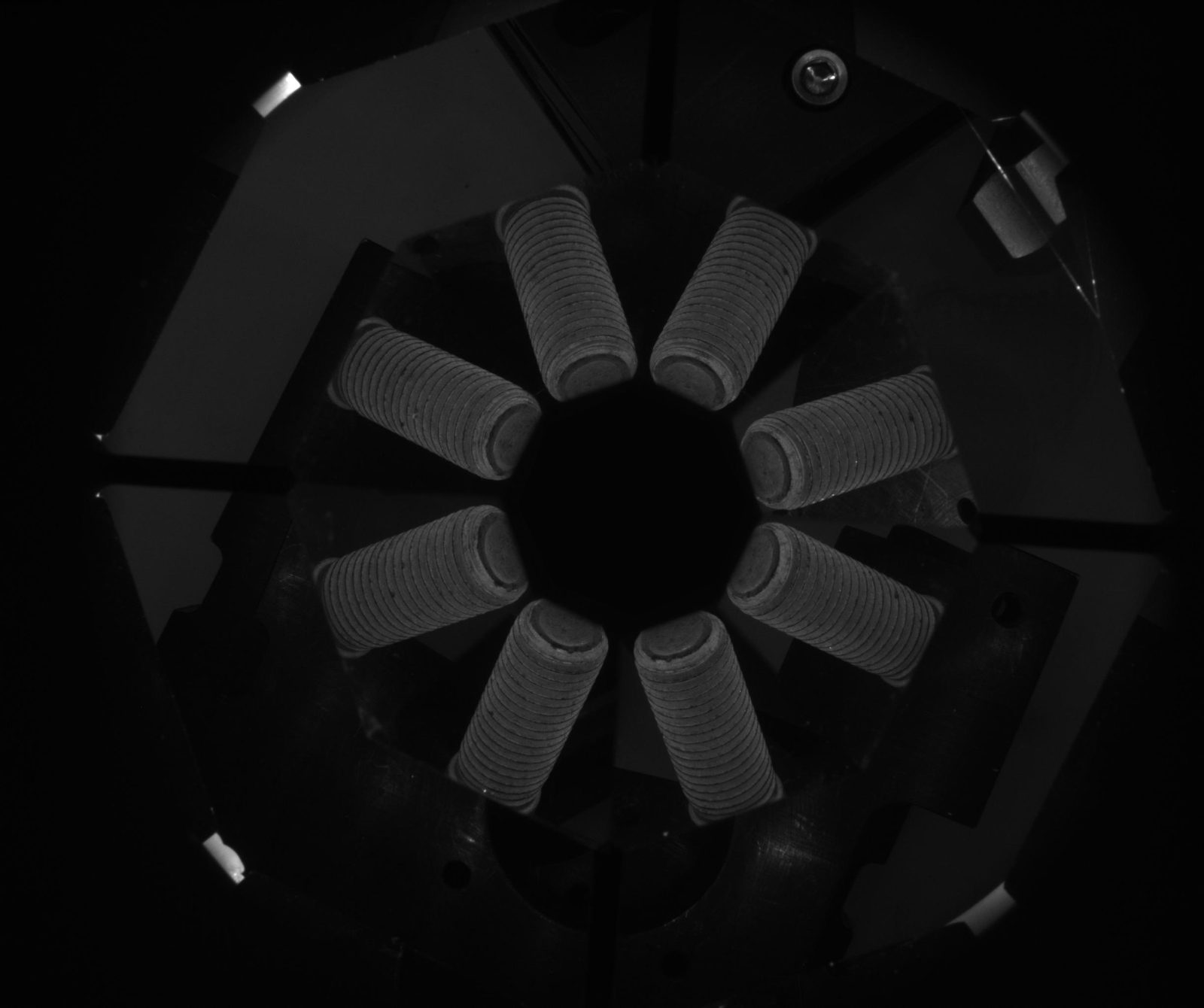
PCPW optics provide eight different views of the side and top surfaces of an object.
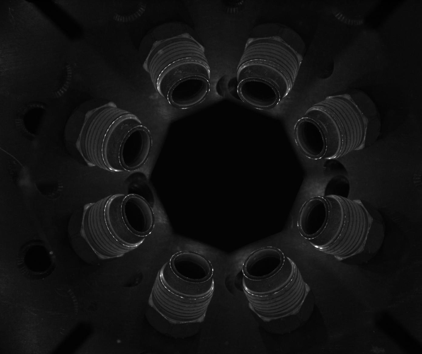
The wide angle of view (45°) enables the inspection of the side features of an object (for example the threads of a screw or a nut) otherwise impossible to acquire with a single camera. Both the external walls of an object and its top can be imaged at the same time, while internal surfaces of hollow objects can be completely inspected from the outside. A combined view of the internal and external surfaces is possible and an image displaying both the inner walls and the bottom of a cavity can be obtained. In addition to these unique features, PCPW optics also ensure excellent image resolution and image brightness.
Notes
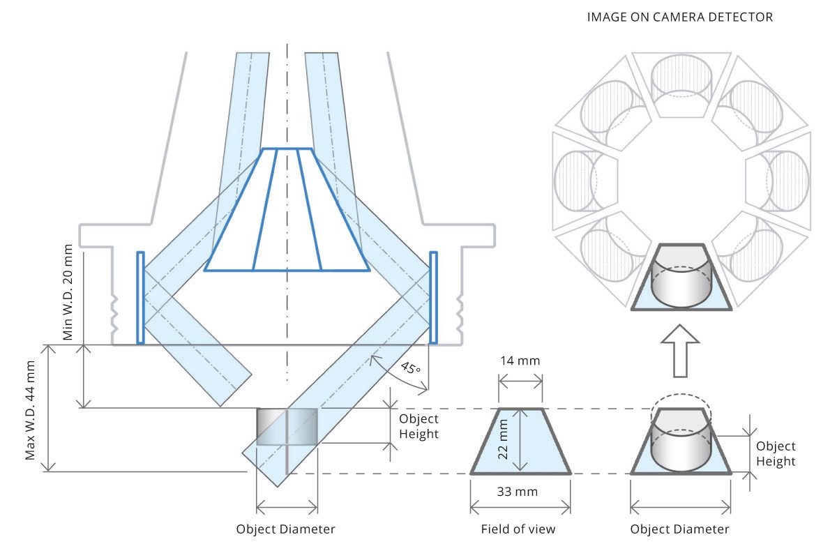
- Working distance: distance between the front end of the mechanics and the object.
- Measured from the front end of the mechanics to the camera flange.
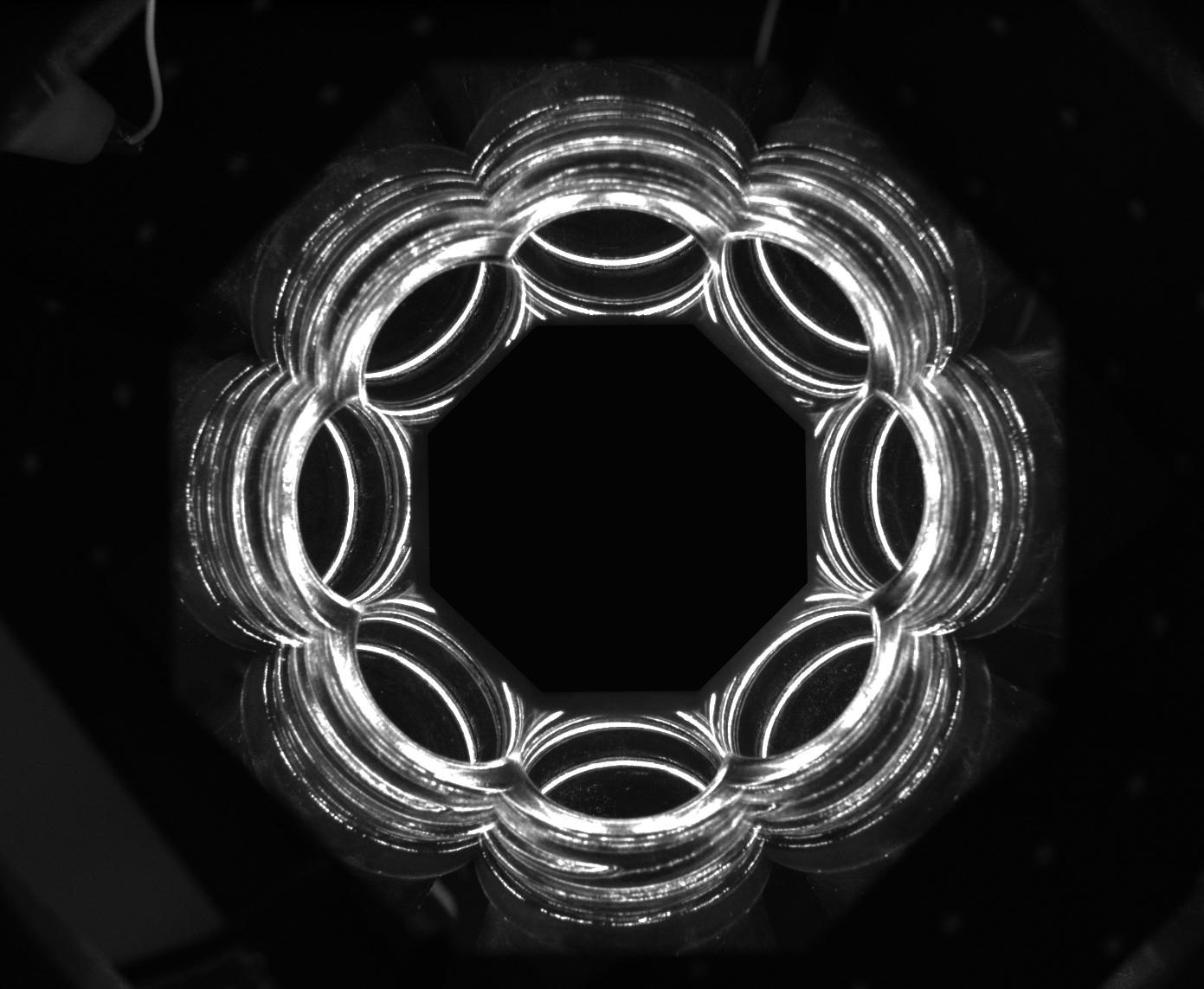
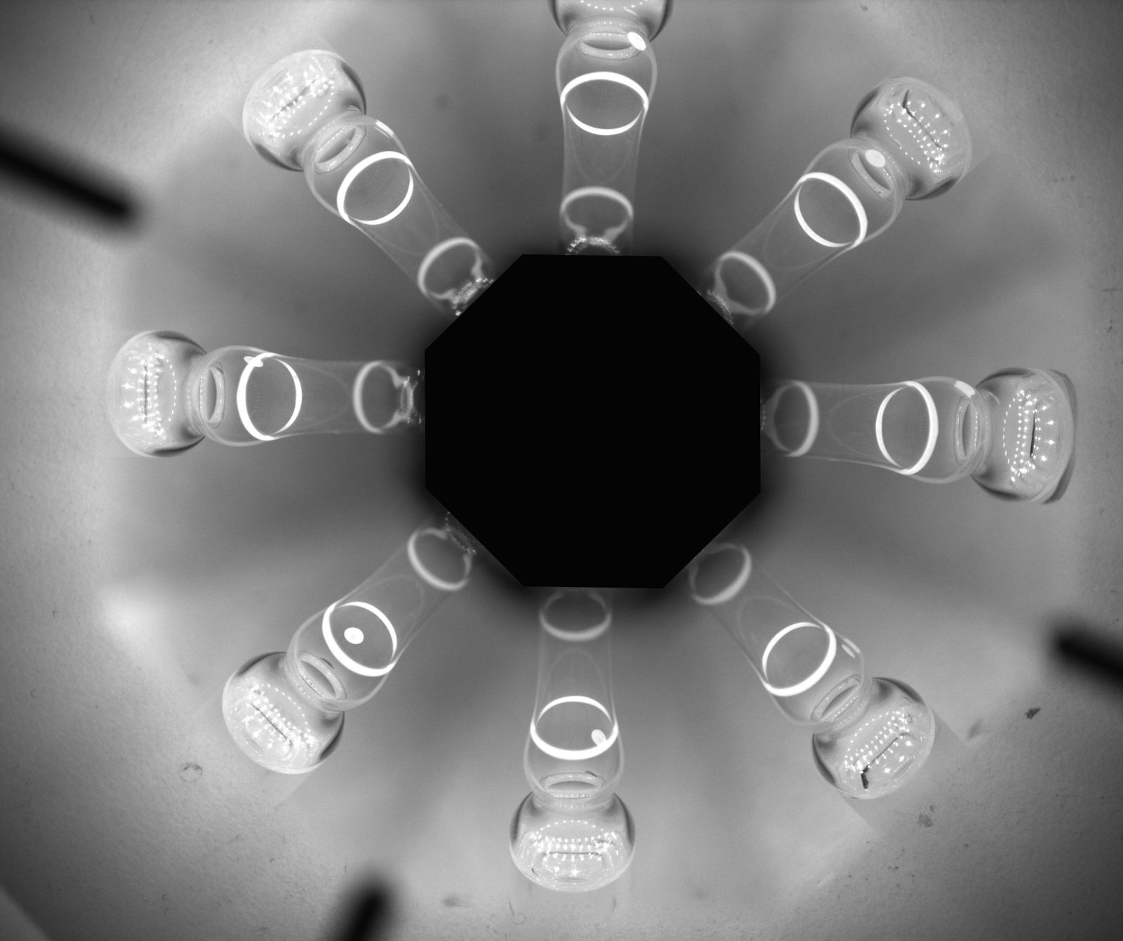
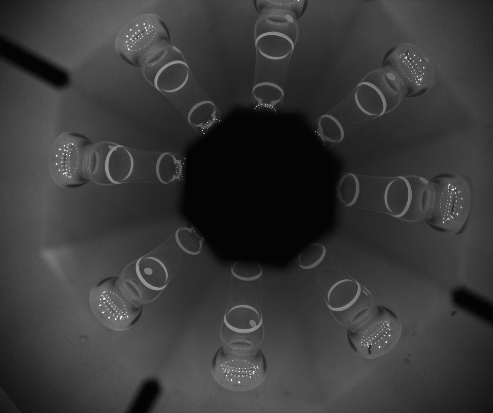
The diagram shows how PCPW optics image a cylindrical object. The object is observed at 45° from eight different points of view. Eight different trapezoidal fields of view are obtained: all the object features included
in such a trapezoid will be imaged on the corresponding image portion. The 45° angle of view allows both the sides and the top of a cylindrical object to be imaged. If the object is a hollow cylinder (hole or cavity), the inner wall
of the cavity will be imaged instead of the top, thus enabling both outer and inner side inspection.
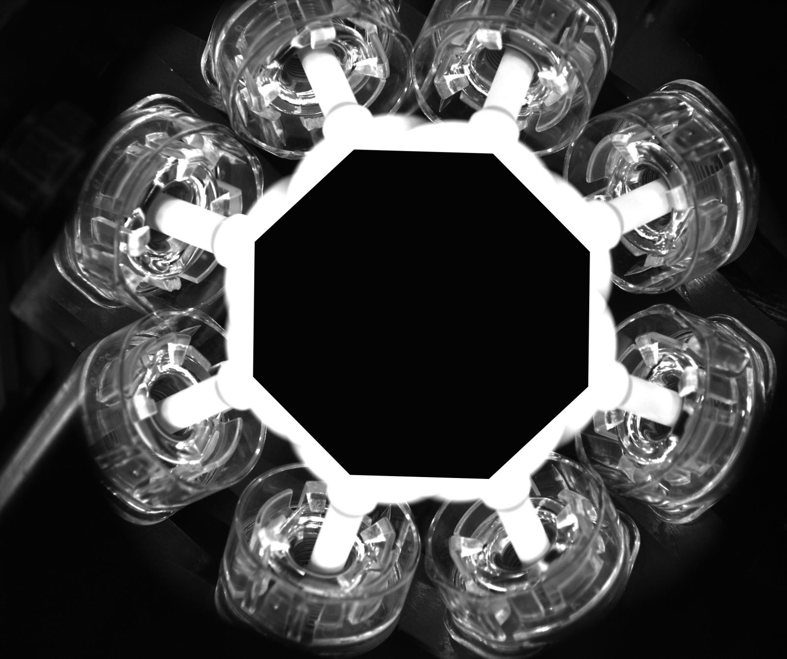
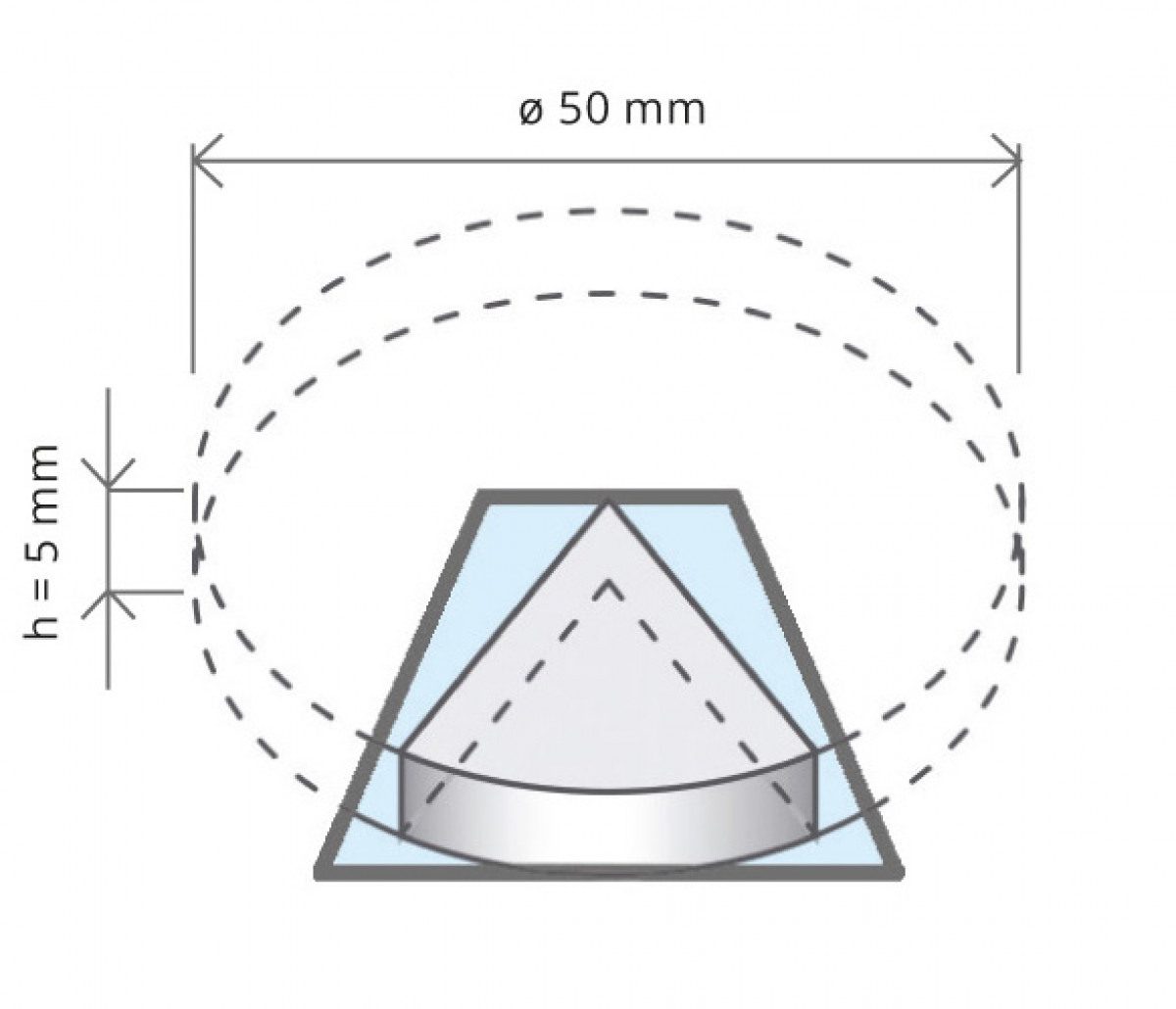
Maximum achievable field of view
In order to perform a complete 360° inspection, each of the eight image portions should image at least 1/6 of the cylindrical surface; this condition ensures a good overlapping between two different lateral views, since part of the object features will be shared by two neighboring image portions..


Video gallery
O-rings and sealings
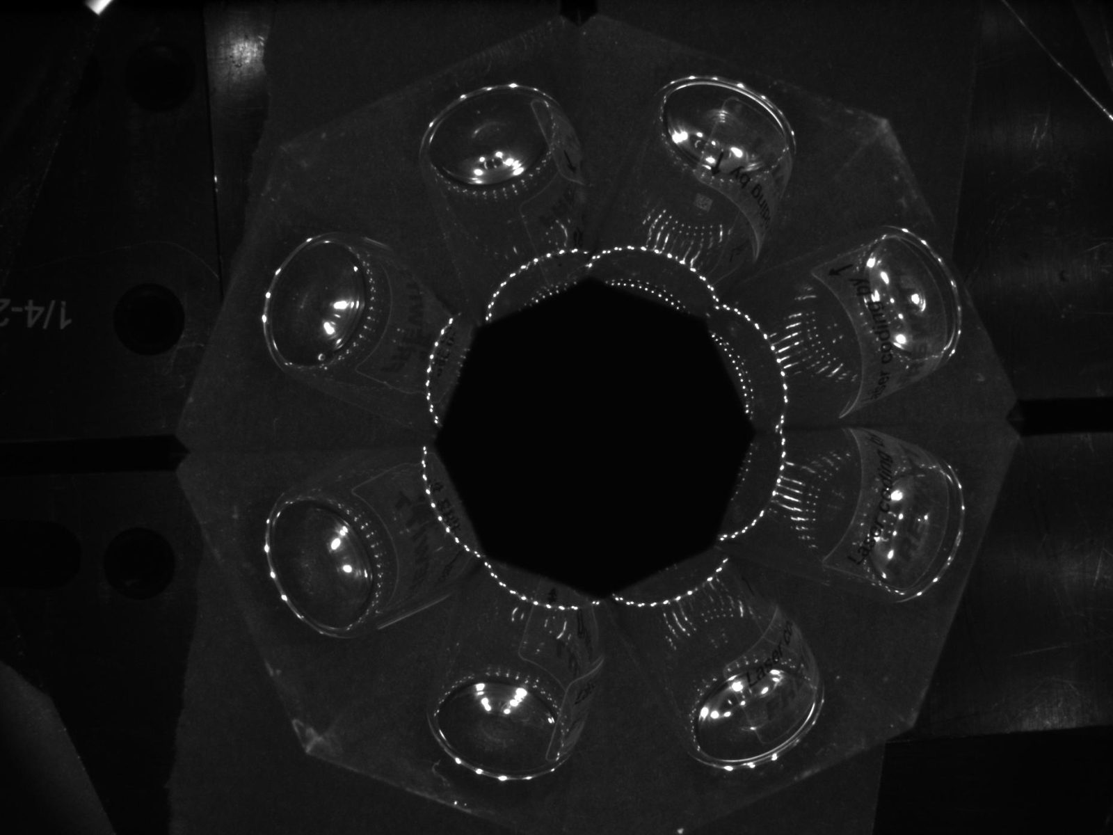
Bottle

Mechanical parts


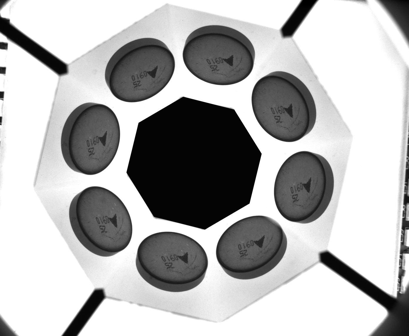
Pharma