Telecentric lenses tutorial
Basic information and working principles
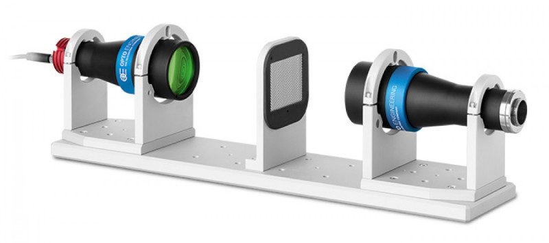
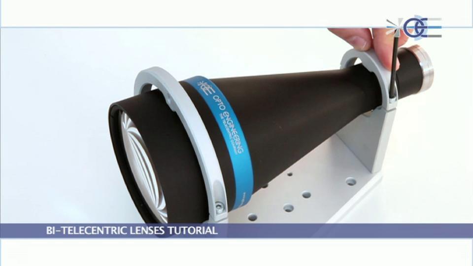
Bi-telecentric lenses tutorial
In recent years the use of machine vision technologies in dimensional measurement applications has become very popular: improvements in cameras, software and illumination components have made it possible to reach accuracies sometimes even better than contact and laser-based methods.
Successful machine vision integrators are increasingly aware that quality optics produce superior system performances and telecentric lenses are required for any dimensional measurement imaging application: software engineers requiring precise measurement of mechanical parts need high contrast images with the lowest possible geometrical distortion; perspective effects, causing change of magnification when the object is not precisely positioned or is highly 3-dimensional, must also be minimized or eliminated.
Besides image processing problems, vision system designers must take in account that common, entocentric optics introduce several factors which limit measurement application accuracy and repeatability:
- magnification changes, due to object displacement
- image distortion
- perspective errors
- poor image resolution
- object edge position uncertainty, due to lighting geometry
Telecentric lenses reduce or even cancel most of these problems, and for this reason have become a key component for all those developing high accuracy gauging applications.
Basic lens types


Magnification constancy
In measurement applications an orthonormal view of the object (i.e. with no object sides imaging) is frequently needed so that correct linear measurements may be performed.
Furthermore, many mechanical parts cannot be precisely positioned (for example, due to vibrations) or a measurement must be performed at different depths or, even worse, the object thickness (and therefore the object surface position) may vary; nevertheless, software engineers do need a perfect correlation between imaged and real dimensions.
Common lenses give different magnifications at different conjugates: as such, when the object is displaced, the size of its image changes almost proportionally with the object-to-lens distance. This is something anybody can easily experience in everyday life, for example when taking pictures with a camera equipped with a standard photographic lens.

With telecentric lenses the image size is left unchanged with object displacement, provided the object stays within a certain range often referred to as “depth of field” or “telecentric range”.
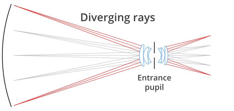
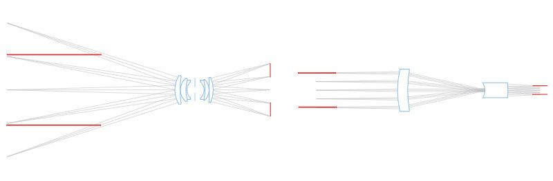
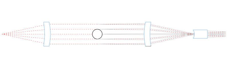
This is due to the particular path of the rays within the optical system: only ray cones whose barycentric ray (or “principal ray”) is parallel to the opto-mechanical main axis are collected by the objective. For this reason, the front lens diameter must be at least as large as the object field diagonal.
This optical behaviour is obtained by positioning the stop aperture exactly on the focal plane of the front optical group: the incoming rays aim at the entrance pupil which appears as being virtually placed at the infinity. The name “telecentric” derives from the words “tele” (which means “far” in ancient Greek) and “centre” which accounts for the pupil aperture, the actual centre of an optical system.
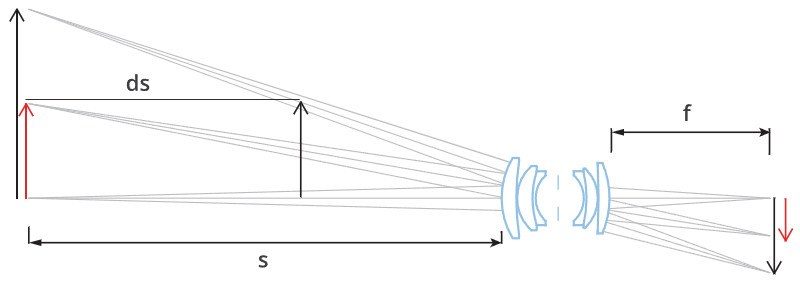
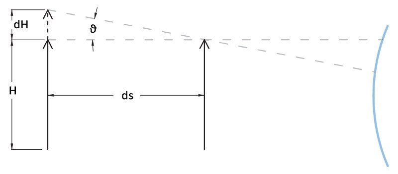
Just to get the feeling of how the two different objective types behave, let us think of a standard lens with a focal length f = 12 mm, interfaced to a 1/3” detector, looking at an object of height H = 20 mm, placed at a distance s = 200 mm.
Assuming an object displacement of ds = 1mm, the change in its dimensions will be around:
dH = (ds/s) · H = (1/200) · 20 mm = 0,1 mm
In a telecentric lens the magnification change is determined by the “telecentric slope”: good telecentric lenses show an effective telecentric slope theta of about 0,1° (0,0017 rad); this means that the object dimensions would only change of about
dH = ds · theta= 1 · 0,0017 mm = 0,0017 mm
for each displacement ds of 1 mm. Thus, with telecentric lenses the magnification error is reduced to 1/10 to 1/100 compared to standard lenses.
The concept of “telecentric range” or “telecentric depth” is often interpreted as the field depth range where magnification remains constant. This is a somewhat misleading interpretation as it implies that the remaining space is “non-telecentric” while this parameter should always be associated with the maximum measurement error caused by the lens within that same range. A much more significant parameter is “telecentric slope” (above referred to as “theta”) or “telecentricity”. Such angle defines the measurement error due to object displacement, no matter where the object is placed: since the principal optical rays “go straight” the error amount is obviously space-independent.
In order to collect telecentric rays, the front optical components of a telecentric lens must be at least as large as the object largest dimension; for this reason telecentric lenses are larger, heavier and therefore more expensive than common optics.
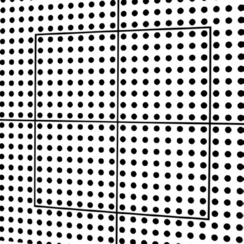
Low distortion
Distortion is one of the worst problems limiting measurement accuracy: even the best performing optics are affected by some grade of distortion, while often even a single pixel of difference between the real image and the expected image could be critical.
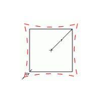
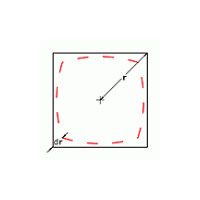
Distortion is simply defined as the percentage difference between the distance of an image point from the image centre and the same distance as it would be measured in a distortion-free image; it can be thought of as a deviation between the imaged and the real dimensions of an object. For instance, if a point of an image is 198 pixels distant from the centre, while a distance of 200 pixels would be expected in absence of distortion, the radial distortion, at that point, would be:
distortion = (198 - 200) / 200 = -2/200 = 1%
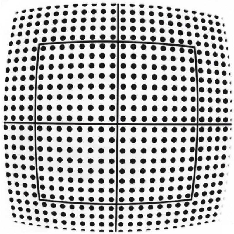
Positive radial distortion is also called “pincushion” distortion, negative radial distortion is called “barrel” distortion: note that the distortion depends on the radial position and can also change of sign. Distortion can be also viewed as a 2D geometrical transformation of the real world into the virtual space created by the lens; as this transformation is not perfectly linear but is approaching 2nd or 3rd degree polynomials, the image becomes slightly stretched and deformed.
Common optics show distortion values ranging from some percent to some tens percent, making precise measurement really difficult; things get even worse when non-telecentric lenses are used. Since most machine vision optics have originally been developed for video-surveillance or photography applications, relevant distortion values have usually been considered acceptable, as the human eye can compensate distortion errors up to 1-2%. In some cases, like in fish-eye lenses or webcam-style lenses, distortion is intentionally introduced to make the lens work on large angles also providing an even illumination of the detector (in these cases distortion is helpful in reducing cosine-to-the-fourth law effects).
High quality telecentric lenses normally show a very low distortion degree, in the range of 0,1%; although this amount seems to be very small it would actually result into measurement errors approaching the size of one pixel of an high resolution camera. For this reason, in most applications, distortion has to be software calibrated: a precise pattern (whose geometrical accuracy must be at least ten times better than the needed measurement accuracy) is placed at the centre of the field depth; distortion is then computed at several image points and, based on these data, the software algorithm transforms the native image into a distortion-free image.
Few people know that the distortion also depends upon the distance of the object, not only upon the optics itself; for this reason it is very important that the nominal working distance is strictly respected.
A fine perpendicular alignment between the lens and the inspected object is recommended in order to avoid non-axially symmetric distortion effects. Trapezoidal distortion (also known as “keystone” or “thin prism” effect) is another important parameter to be minimized in an optical inspection system as it is asymmetric and very difficult to software calibrate. Lens focusing mechanism can also introduce some symmetric or non-symmetric distortion effect because of mechanical play or optical element decentreing.

Perspective errors limitation
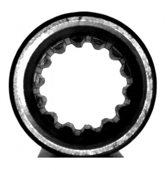
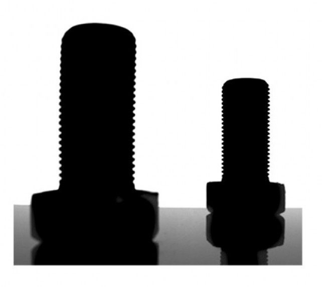
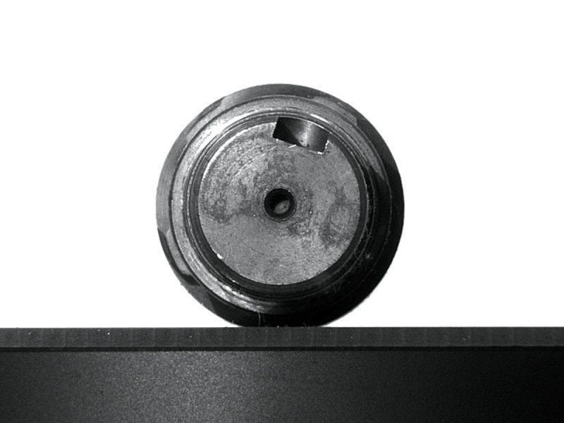
When using common optics to image 3D objects (non completely flat objects) far objects will look smaller than close objects. As a consequence, when objects like a cylindrical cavity are imaged, the top and the bottom crown edges will appear to be concentric although the two circles are perfectly identical.
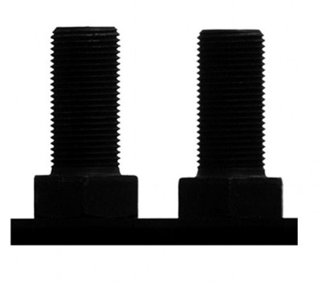
On the contrary, by means of a telecentric lens, the bottom crown edge will disappear because the two crown edges are perfectly overlapping.
This effect is due to the specific path of the rays: in the case of common optics, any geometric information that is “parallel” to the main optical axis also shows a component on the detector plane direction, while in a telecentric lens this perpendicular component is totally absent.
One could describe a common lens as a mathematical function building a correspondence between the 3-dimensional object space and the 2-dimensional detector (image) space while a telecentric would build a 2D-2D correspondance as would not display an object’s third dimension thus making it the perfect component for profile imaging and measurement.


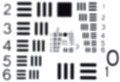
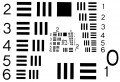
Good image resolution
Image resolution is decribed by CTF (contrast transfer function) which quantifies the contrast ratio at a given spatial frequency on the camera detector plane, expressed in lp/mm (line pairs per millimeter).
Quite often, machine vision integrators tend to combine cameras having tons of small pixels with cheap, poor resolution lenses, resulting in blurred images; the resolution provided by telecentric lenses is compatible with very small pixel sizes and high resolution cameras thus increasing the measurement resolution.
No edge position uncertainty
When back lighting an object it can often be difficult to determine the exact position of its edges.
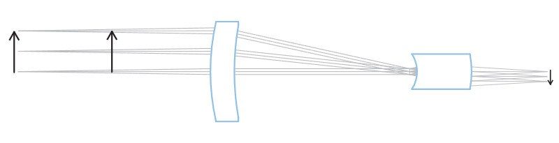
This can happen because the bright pixels in the background tend to overlap with the dark pixels at the object edges. Moreover, if the object is highly 3D-shaped, also a border effect could furtherly limit the measurement precision; as shown in the following drawing, rays grazing the object edges at certain incidence angles could be reflected by the surface, but still be collected by the lens.
The lens would then see those rays as if they were coming from behind the object; as a result, slices of the image could disappear, thus making the measurement very much imprecise and unstable.

This effect can be efficiently limited by means of a telecentric lens: if the pupil aperture is small enough, the only reflected rays which could enter the lens would be those nearly parallel to the optical main axis.
As these rays are affected by very small deflection, the reflection from the object surface doesn’t jeopardize the measurement accuracy.
To get rid of such issues, collimated (also called “telecentric”) illuminators can be interfaced to telecentric lenses, taking care of matching the lens aperture and FOV with the collimated source divergence. With this option, all the light coming out of the illuminator is collected by the lens and delivered onto the detector, allowing extremely high signal-to-noise ratios and incredibly low exposure times. On the other hand, only “expected” rays come into the imaging lens so that no problems occur at the borders.
Benefits of bi-telecentric lenses
1. Better Magnification Constancy
Standard telecentric lenses accept ray cones whose axis is parallel to the main optical axis; if the lens is only telecentric in object space, ray cones passing through the optical system reach the detector from different angles depending upon the field position. Moreover the optical wavefront is completely asymmetric since incoming telecentric rays become non-telecentric in image space. As a consequence, the spots generated by ray cones on the detector plane change in shape and dimension from point to point in image space (the point-spread function becomes non-symmetrical and a small circular spot grows larger and turns elliptical as you move from the image centre towards the borders).
Even worse, when the object is displaced, rays coming from a certain field point generate a spot that moves back and forth over the image plane, thus causing a significant change in magnification. For this reason non bi-telecentric lenses show a lower magnification constancy although their telecentricity might be very good if measured only in the object space.
Bi-telecentric lenses are telecentric in both object and image space, which means that principal rays are parallel not only when entering but also when exiting the lens.
This feature is essential to overcome all the accuracy issues concerned with mono-telecentric lenses such as point spread function inhomogeneity and lack of magnification constancy through the field depth.

2. Increased Field Depth
Field depth is the maximum acceptable displacement of an object from its best focus position. Beyond this limit the image resolution becomes poor, because the rays coming from the object can’t create sufficiently small spots on the detector: blurring effect occurs because geometrical information carried by the optical rays spread over too many image pixels. Depth of field basically depends upon the optics F/#, which is inversely proportional to the lens aperture diameter: the higher the f-number the larger the field depth, with a quasi-linear dependence. Increasing the F/# reduces ray cones divergence, allowing for smaller spots to form onto the detector; however raising the F/# over certain values introduces diffraction effects which limit the maximumachievable resolution.
Bi-telecentricity is beneficial in maintaining a very good image contrast even when looking at very thick objects: the symmetry of the optical system and the rays parallelism help the image spots with staying symmetrical, which reduces the blur effect. This results in a field depth being perceived as 20-30% larger compared to non bi-telecentric optics.
3. Even detector illumination
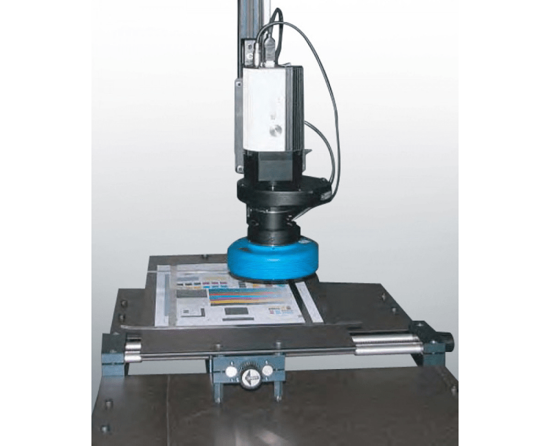
Bi-telecentric lenses boast a very even illumination of the detector, which comes useful in several applications such as LCD, textile and print quality control.
When dichroic filters have to be integrated in the optical path for photometric or radiometric measurements, bi-telecentricity assures that the ray fan axis strikes the filter normal to its surface, thus preserving the optical band-pass over the whole detector area.
When telecentric lenses should be used
- When a thick object (thickness > 1/10 FOV diagonal) must be measured
- When different measurements on different object planes must be carried out
- When the object-to-lens distance is not exactly known or cannot be predicted
- When holes must be inspected or measured
- When the profile of a piece must be extracted
- When the image brightness must be very even
- When a directional illumination and a directional “point of view” are required.