Specifications
Downloads
Compatible products
| Main optical specifications | ||
| Magnification | (x) | 0.110 |
| Image shape dimension (1) | (Ø, x=mm) | Ø=11.1, x=9.6 |
| Max sensor size | 2/3″ | |
| Object field of view | ||
| 1/3” - 4.80 x 3.60 | (mm × mm) | 43.64 x 32.73 |
| 1/2.5” - 5.70 x 4.28 | (mm × mm) | 51.82 x 38.91 |
| 1/2” - 6.40 x 4.80 | (mm × mm) | 58.18 x 43.64 |
| 1/1.8” - 7.13 x 5.33 | (mm × mm) | 64.82 x 48.45 |
| 2/3” - 8.50 x 7.09 | (mm × mm) | 77.27 x 64.45 |
| Advanced optical specifications | ||
| Working distance (2) | (mm) | 226.8 |
| Working ƒ/N (3) | 8 | |
| Telecentricity typical (max) (4) | (deg) | < 0.04 (0.08) |
| Distortion typical (max) (5) | (%) | < 0.02 (0.10) |
| Depth of field (6) | (mm) | 34.20 |
| Resolution (7) | (μm) | 46 |
| Electrical specifications | ||
| Light color, peak wavelength | green, 520 nm | |
| Supply voltage | (V) | 12-24 |
| Max power consumption | (W) | 2.5 |
| LED voltage (8) | (V) | 2.8 (-) |
| LED current (9) | (mA) | 350 |
| Max pulse current (10) | (mA) | 2000 |
| Mechanical specifications | ||
| Mount | C | |
| Phase adjustment | Yes | |
| Length | (mm) | 578 |
| Width (11) | (mm) | 193 |
| Height | (mm) | 162 |
| Mass | (g) | 11373 |
| Environmental specifications | ||
| Operating temperature | (°C) | 0-40 |
| Storage temperature | (°C) | 0-50 |
| Operating relative humidity | (%) | 20-85, non condensing |
| Installation | Indoor use only | |
| Eye safety | ||
| Risk group according to CEI EN 62471:2010 | Exempt | |
Last update 23 Aug 2024
Notes
- Indicates the dimensions and shape of image, where "Ø =" stands for diameter and "x=" indicates the nominal image height and length (Tech Info for related drawing).
- Working distance: distance between the front end of the mechanics and the object. Set this distance within ±3% of the nominal value for maximum resolution and minimum distortion.
- Working f-number (wf/N): the real f-number of a lens in operating conditions.
- Maximum angle between chief rays and optical axis on the object side. Typical (average production) values and maximum (guaranteed) values are listed.
- Percent deviation of the real image compared to an ideal, undistorted image. Typical (average production) values and maximum (guaranteed) values are listed.
- At the limits of the depth of field, the image can still be used for measurements. For a very sharp image, however, only half of the depth of field should be considered. Pixel size used for calculation is 3.45 μm.
- Object side, calculated with the Rayleigh criterion with λ= 520 nm
- At max forward current. Tolerance is ± 0.06V on forward voltage measurements.
- Used in continuous (not pulsed) mode.
- At pulse width <= 10 ms, duty cycle <= 10% condition. Built-in electronics board must be bypassed (see tech info).
- Maximum width dimension considering illuminator/telecentric side and cable connector end
All product specifications and data are subject to change without notice to improve reliability, functionality, design or other. Photos and pictures are for illustration purposes only.
Despite the efforts made to generate an error-free compatibility list, we always recommend to consult the Opto Engineering® technical support department before purchasing a compatible product. Opto Engineering® shall not be liable for any damage or malfunctioning caused by the incorrect selection of a compatible product.

ITA50-GM-10C
Area scan camera 2464 x 2056 MP, Sony IMX264, CMOS Global shutter, 2/3", Mono, 1 GigE, POE, C mount
ITA50-GC-10C
Area scan camera 2464 x 2056 MP, Sony IMX264, CMOS Global shutter, 2/3", Color, 1 GigE, POE, C mount
ITA50-GM-10C-PL
Area scan camera 2464 x 2056 MP, Sony IMX264, CMOS Global shutter, 2/3", Polar Mono, 1 GigE, POE, C mount
ITA50-GC-10C-PL
Area scan camera 2464 x 2056 MP, Sony IMX264, CMOS Global shutter, 2/3", Polar Color, 1 GigE, POE, C mount
ITA81-GM-20C
Area scan camera 2856 x 2848 MP, Sony IMX546, CMOS Global shutter, 2/3", Mono, 1 GigE, POE, C mount
ITA81-GC-20C
Area scan camera 2856 x 2848 MP, Sony IMX546, CMOS Global shutter, 2/3", Color, 1 GigE, POE, C mount
LTSCHP1W-G
Replacement LED module, green
LTSCHP1W-GZ
Replacement LED module with diffuser, green

CB244P1500
Power cable, side 1 M8 connector straight, side 2 cable end - 2 m - type 1 labels
CB244P1500L
Power cable, side 1 M8 connector angled, side 2 cable end - 2 m - type 1 labels
Request a quote
Add this product to the quote request list.
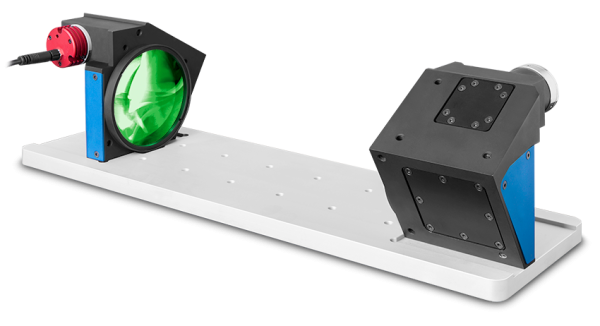
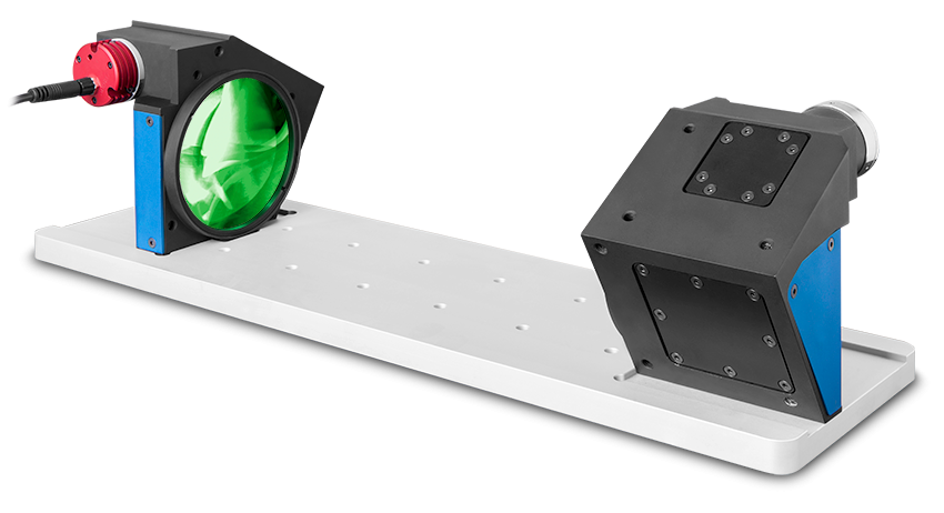
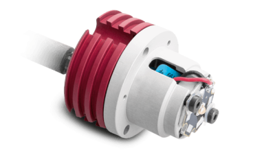
Product images