Image quality
Aberrations
“Aberrations” is a general category including the principal factors that cause an optical system to perform differently than the ideal case. There are a number of factors that do not allow a lens to achieve its theoretical performance.
Physical aberrations
The homogeneity of optical materials and surfaces is the first requirement to achieve optimum focusing of light rays and proper image formation. Obviously, homogeneity of real materials has an upper limit determined by various factors (e.g. material inclusions), some of which cannot be eliminated. Dust and dirt are external factors that certainly degrade a lens performance and should thus be avoided as much as possible.
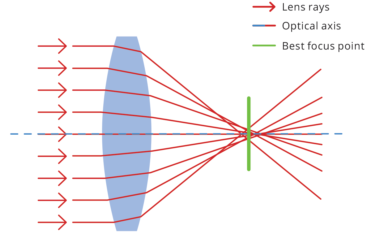
Spherical aberrations
Spherical lenses are very common because they are relatively easy to
manufacture. However, the spherical shape is not ideal for perfect
imaging - in fact, collimated rays entering the lens at different
distances from the optical axis will converge to different points,
causing an overall loss of focus. Like many optical aberrations, the
blur effect increases towards the edge of the lens.
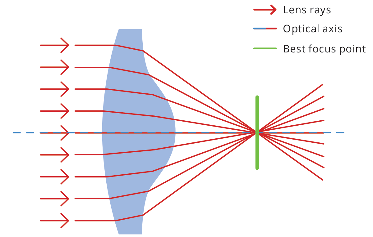
To reduce
the problem, aspherical lenses (Fig. 16) are often used - their surface
profile is not a portion of a sphere or cylinder, but rather a more
complex profile apt to minimize spherical aberrations. An alternative
solution is working at high F/#’s, so that rays entering the lens far
from the optical axis and causing spherical aberration cannot reach the
sensor.
Chromatic aberration
The refractive index of a material is a number that describes the
scattering angle of light passing through it – essentially how much rays
are bent or refracted - and it is a function of the wavelength of
light. As white light enters a lens, each wavelength takes a slightly
different path. This phenomenon is called dispersion and produces the
splitting of white light into its spectral components, causing chromatic
aberration. The effect is minimal at the center of the optics, growing
towards the edges.
Chromatic aberration causes color fringes to appear across the image, resulting in blurred edges that make it impossible to correctly image object features. While an achromatic doublet can be used to reduce this kind of aberration, a simple solution when no color information is needed is using monochrome light. Chromatic aberration can be of two types: longitudinal (Fig. 17) and lateral (Fig. 18), depending on the direction of incoming parallel rays.


Astigmatism
Astigmatism is an optical aberration that occurs when rays lying in two perpendicular planes on the optical axis have different foci. This causes blur in one direction that is absent in the other direction. If we focus the sensor for the sagittal plane, we see circles become ellipses in the tangential direction and vice versa.

Coma
Coma aberration occurs when parallel rays entering the lens at a certain angle are brought to focus at different positions, depending on their distance from the optical axis. A circle in the object plane will appear in the image as a comet-shaped element, which gives the name to this particular aberration effect.
Field curvature
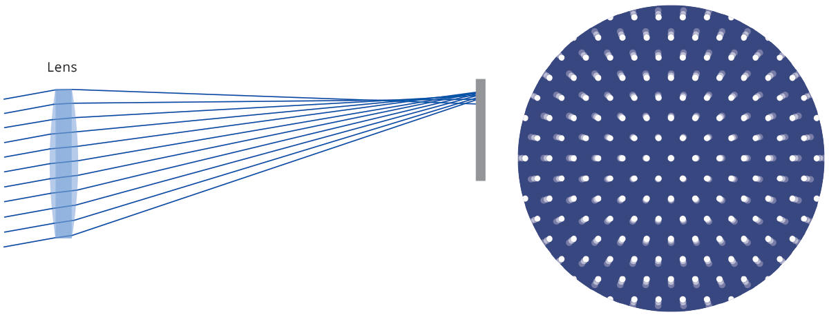
Field curvature aberration describes the fact that parallel rays
reaching the lens from different directions do not focus on a plane, but
rather on a curved surface.
This causes radial defocusing, i.e. for a given sensor position, only a circular crown will be in focus.

Distortion
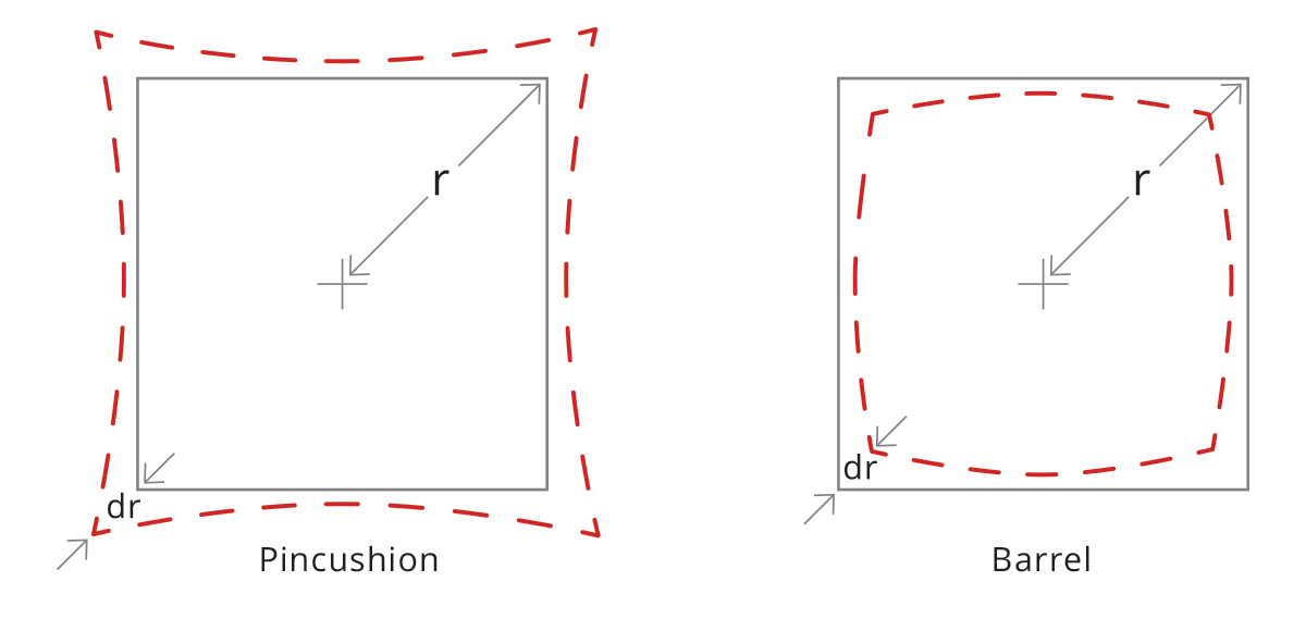
With a perfect lens, a squared element would only be transformed in size, without affecting its geometric properties. Conversely, a real lens always introduces some geometric distortion, mostly radially symmetric (as a reflection of the radial symmetry of the optics). This radial distortion can be of two kinds: barrel and pincushion distortion. With barrel distortion, image magnification decreases with the distance from the optical axis, giving the apparent effect of the image being wrapped around a sphere. With pincushion distortion image magnification increases with the distance from the optical axis. Lines that do not pass through the center of the image are bent inwards, like the edges of a pincushion.
What about distortion correction?
Since telecentric lenses are a real-world object, they show some residual distortion which can affect measurement accuracy. Distortion is calculated as the percent difference between the real and expected image height and can be approximated by a second-order polynomial. If we define the radial distances from the image center as follows
the distortion is computed as a function of Ra:
where a, b and c are constant values that define the distortion curve behavior; note that “a” is usually zero as the distortion is usually zero at the image center. In some cases, a third-order polynomial could be required to get a perfect fit for the curve.
In addition to radial distortion, also trapezoidal distortion must be taken into account. This effect can be thought of as the perspective error due to the misalignment between optical and mechanical components, whose consequence is to transform parallel lines in object space into convergent (or divergent) lines in image space.
Such an effect, also known as “keystone” or “thin prism”, can be easily fixed by means of pretty common algorithms which compute the point where convergent bundles of lines cross each other.
An interesting aspect is that radial and trapezoidal distortion are two completely different physical phenomena, hence they can be mathematically corrected by means of two independent space transform functions that can also be applied subsequently.
An alternative (or additional) approach is to correct both distortions locally and at once: the image of a grid pattern is used to define the distortion error amount and its orientation zone by zone. The final result is a vector field where each vector associated with a specific image zone defines what correction has to be applied to the x,y coordinate measurements within the image range.
Why green light is recommended for telecentric lenses?
All lenses operating in the visible range, including Opto Engineering® telecentric lenses, are achromatized through the whole VIS spectrum. However, parameters related to the lens distortion and telecentricity are typically optimized for the wavelengths at the center of the VIS range, which is green light. Moreover, the resolution tends to be better in the green light range, where the achromatization is almost perfect. “Green” is also better than “Red” because a shorter wavelength range increases the diffraction limit of the lens and the maximum achievable resolution.
Contrast
Defects and optical aberrations, together with diffraction, contribute to image quality degradation. An efficient way to assess image quality is to calculate contrast, that is the difference in luminance that makes an object - its representation in the image or on a display - distinguishable. Mathematically, contrast is defined as
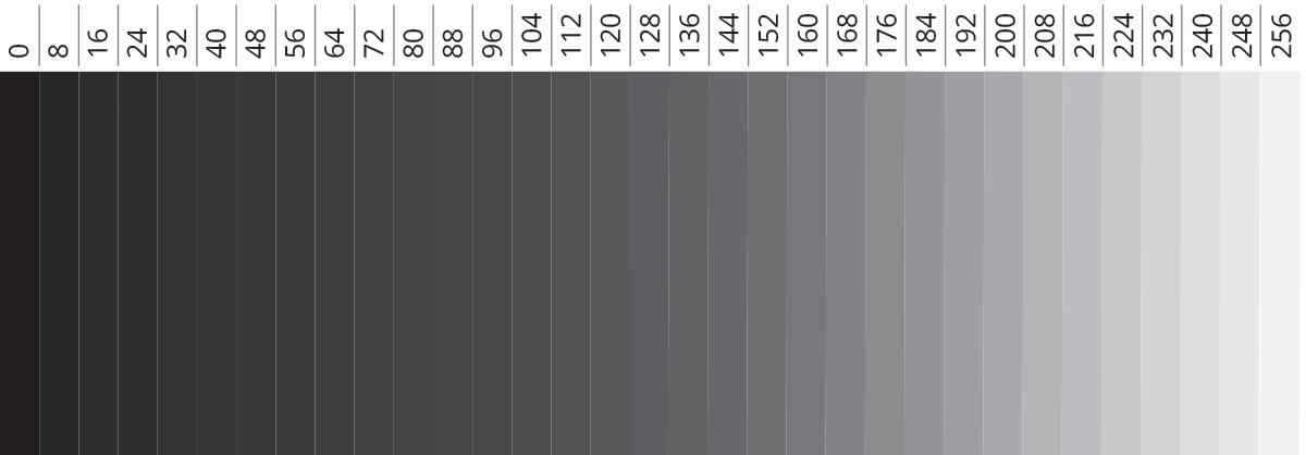
where Imax (Imin) is the highest (lowest) luminance. In a digital image, ‘luminance’ is a value that goes from 0 (black) to a maximum value depending on color depth (number of bits used to describe the brightness of each color). For typical 8-bit images (in grayscale, for the sake of simplicity), this value is 2^8 -1 = 255, since this is the number of combinations (counting from the zero ‘black’ string) one can achieve with 8 bits sequences, assuming 0-1 values for each.
Lens resolving power: transfer function
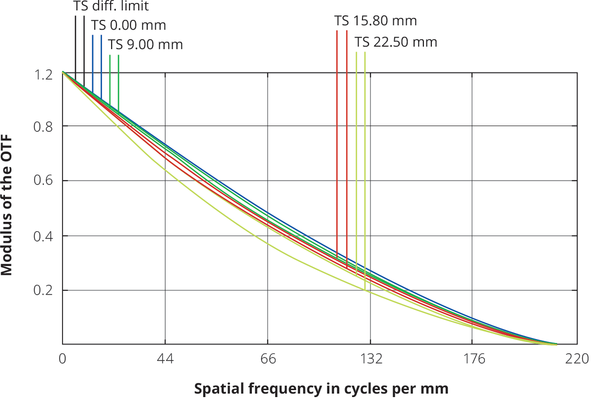
The image quality of an optical system is usually expressed by its transfer function (TF). TF describes the ability of a lens to resolve features, correlating the spatial information in object space (usually expressed in line pair per millimeter) to the contrast achieved in the image.
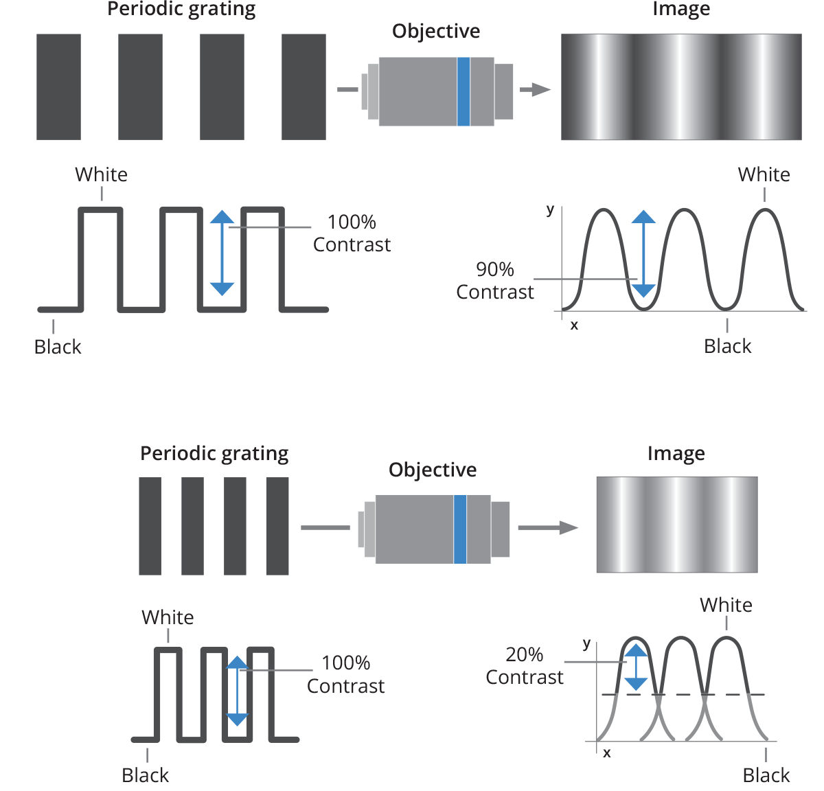
What's the difference between MTF (Modulation Transfer Function) and CTF (Contrast Transfer Function)? CTF expresses the lens contrast response when a “square pattern” (chessboard style) is imaged; this parameter is the most useful in order to assess edge sharpness for measurement applications. On the other hand, MTF is the contrast response achieved when imaging a sinusoidal pattern in which the grey levels range from 0 and 255; this value is more difficult to convert into any useful parameter for machine vision applications. The resolution of a lens is typically expressed by its MTF (modulation transfer function), which shows the response of the lens when a sinusoidal pattern is imaged.
However, the CTF (Contrast Transfer Function) is a more interesting parameter, because it describes the lens contrast when imaging a black and white stripe pattern, thus simulating how the lens would image the edge of an object. If t is the width of each stripe, the relative spatial frequency w will be
For example, a black and white stripe pattern with 5 µm wide stripes has a spatial frequency of 100 lp/mm. The “cut-off frequency” is defined as the value w for which CTF is zero, and it can be estimated as
For example, an Opto Engineering® TC23036 lens (WF/#h F/8) operating
in green light (λ = 0.000587 mm) has a cut-off spatial frequency of
about
Optics and sensor resolution
The cutoff spatial frequency is not an interesting parameter since machine vision systems cannot reliably resolve features with very low contrast. It is thus convenient to choose a limit frequency corresponding to 20% contrast.
A commonly accepted criterion to describe optical resolution is the Rayleigh criterion, which is connected to the concept of resolution limit. When a wave encounters an obstacle - e.g. it passes through an aperture - diffraction occurs. Diffraction in optics is a physical consequence of the wave-like nature of light, resulting in interference effects that modify the intensity pattern of the incoming wavefront.
Since every lens is characterized by an aperture stop, the image quality will be affected by diffraction, depending on the lens aperture: a dot-like object will be correctly imaged on the sensor until its image reaches a limit size; anything smaller will appear to have the same image – a disk with a certain diameter depending on the lens F/# and on the light wavelength.
This circular area is called the Airy disk, having a radius of
where λ is the light wavelength, f is the lens focal length, d is the aperture diameter and f /d is the lens F-number. This also applies to distant objects that appear to be small.
If we consider two neighboring objects, their relative distance can be considered the “object” that is subject to diffraction when it is imaged by the lens. The idea is that the diffraction of both objects’ images increases to the point that it is no longer possible to see them as separate. As an example, we could calculate the theoretical distance at which human eyes cannot distinguish that a car’s lights are separated. The Rayleigh criterion states that two objects are not distinguishable when the peaks of their diffraction patterns are closer than the radius of the Airy Disk rA (in image space).
The Opto Engineering® TC12120 telecentric lens, for example, will not distinguish feature closer than

in image space (e.g. on the sensor). The minimum resolvable size in image space is always 2 rA, regardless of the real-world size of the object. Since the TC12120 lens has 0.052X magnification and 2rA = 11.4 µm, the minimum real-world size of the object that can be resolved is 11.4 µm /0.052 = 220 µm.
For this reason, optics should be properly matched to the sensor and vice versa: in the previous example, there is no advantage to use a camera with 2 µm pixel size, since every “dot-like” object will always cover more than one pixel. In this case, a higher resolution lens or a different sensor (with larger pixels) should be chosen. On the other hand, a system can be limited by the pixel size, where the optics would be able to “see” much smaller features.
The Transfer Function of the whole system should then be considered, assessing the contribution from both the optics and the sensor. It is important to remember that the actual resolution limit is not only given by the lens F/# and the wavelength, but also depends on the lens aberrations: hence, the real spatial frequency to be taken into account is the one described by the MTF curves of the desired lens.
Reflection, transmission, and coatings
When light encounters a surface, a fraction of the beam is reflected,
another fraction is refracted (transmitted) and the rest is absorbed by
the material. In lens design, we must achieve the best transmission
while minimizing reflection and absorption. While absorption is usually
negligible, reflection can be a real problem: the beam is in fact not
only reflected when entering the lens (air-glass boundary) but also when
it exits the lens (glass-air). Let’s suppose that each surface reflects
3% of incoming light: in this case, a two-lens system has an overall
loss of 3*3*3*3 % ~ 89%. Optical coatings – one or more thin layers of
material deposited on the lens surface – are the typical solution: a few
microns of material can dramatically improve image quality, lowering
reflection and improving transmission.
Transmission depends considerably on the light wavelength: different kind of glasses and coatings helps to improve performance in particular spectral regions, e.g. UV or IR. Generally, good transmission in the UV region is more difficult to achieve.
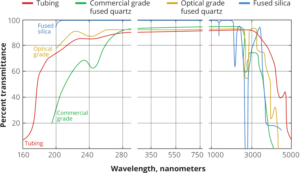
Anti-reflective (AR) coatings are thin films applied to surfaces to reduce their reflectivity through optical interference. An AR coating typically consists of a carefully constructed stack of thin layers with different refractive indices. The internal reflections of these layers interfere with each other so that a wave peak and a wave trough come together and extinction occurs, leading to an overall reflectance that is lower than that of the bare substrate surface.
Anti-reflection coatings are included on most refractive optics and are used to maximize throughput and reduce ghosting. Perhaps the simplest, most common anti-reflective coating consists of a single layer of Magnesium Fluoride (MgF2), which has a very low refractive index (approx. 1.38 at 550 nm).
Hard carbon anti-reflective HCAR coating: HCAR is an optical coating commonly applied to Silicon and Germanium designed to meet the needs of those applications where optical elements are exposed to harsh environments, such as military vehicles and outdoor thermal cameras.
This coating offers highly protective properties coupled with good anti-reflective performance, protecting the outer optical surfaces from high-velocity airborne particles, seawater, engine fuel and oils, high humidity, improper handling, etc.. It offers great resistance to abrasion, salts, acids, alkalis, and oil.
Vignetting
Light that is focused on the sensor can be reduced by a number of internal factors, that do not depend on external factors.
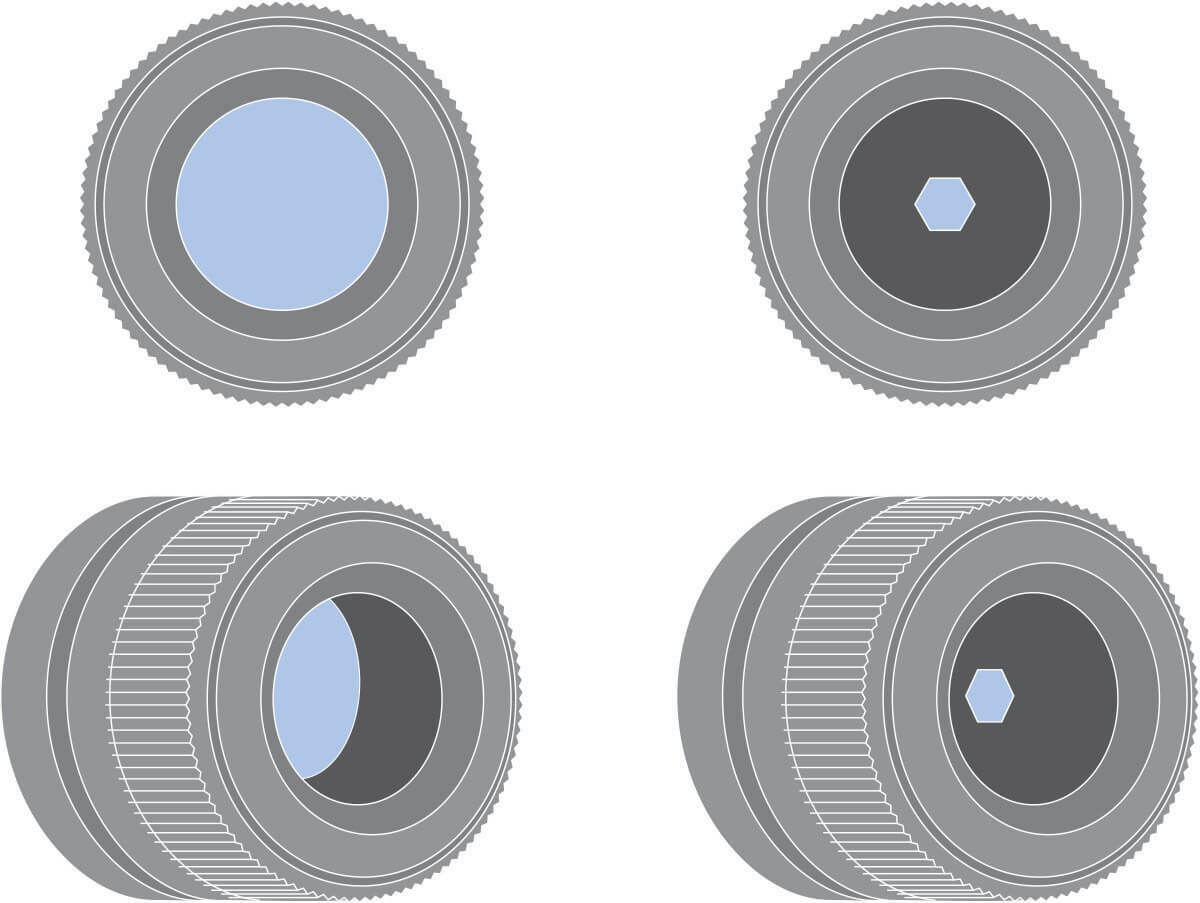
Mount vignetting occurs when light is physically blocked on its way to the sensor. Typically this happens when the lens image circle (cross-section of the cone of light projected by the lens) is smaller than the sensor size so that a number of pixels are not hit by light, thus appearing black in the image. This can be avoided by properly matching optics to sensors: for example, a typical 2/3” sensor (8.45 x 7.07 mm, 3.45 µm pixel size) with 11 mm diagonal would require a lens with a (minimum) image circle of 11 mm in diameter.
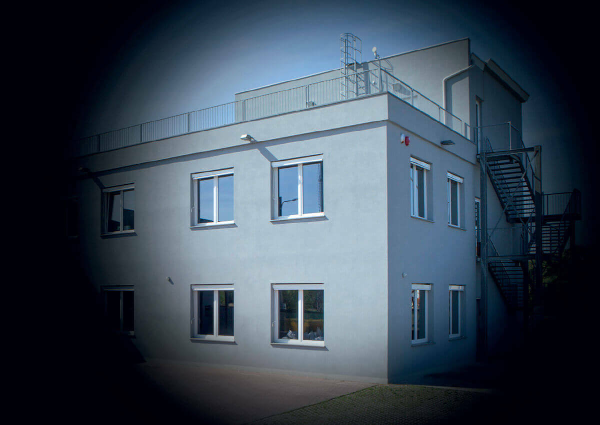
Aperture vignetting is connected to the optics F/#: a lens with a higher F/# (narrower aperture) will receive the same light from most directions, while a lens with a lower F/# will not receive the same amount of light from wide angles, since light will be partially blocked by the edges of the physical aperture.
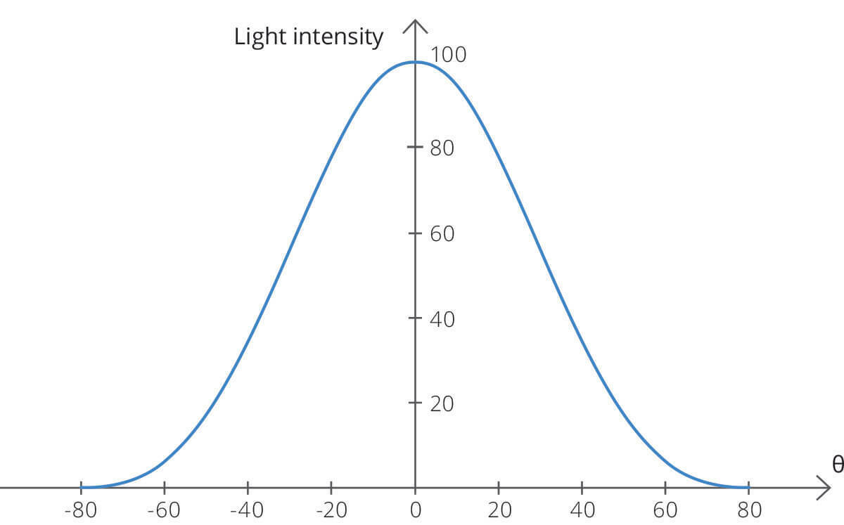
Cos4 vignetting describes the natural light falloff caused by light rays reaching the sensor at an angle. The light falloff is described by the cos^4(θ) function, where θ is the angle of incoming light with respect to the optical axis in image space. The drop in intensity is more significant at wide incidence angles, causing the image to appear brighter at the center and darker at the edges.
