More info
Wavelength and optical performance
The performance of an optical system is influenced by the wavelength of the light used.
When designing an optical system, you can choose whether to optimize it on a single wavelength or on a range of wavelengths.
The wider the desired wavelength range, the more complex the optical system must be in order to correct chromatic aberrations (for example by using achromatic doublets, a larger number of lenses and more complex optical glasses). It is therefore preferable, where possible, to use monochromatic lighting: this simplifies the optical system, reducing the number of components in favor of greater stability and efficiency.
Choosing the wavelength is never an easy task and may depend on various factors, including
- the surface of the sample, which can be opaque or reflective for some wavelengths
- the desired resolution: the shorter the wavelength, the greater the theoretical resolution of the system
- the maximum complexity allowed for the system itself, determined by the maximum cost of the system
- the availability of an illuminator of the desired wavelength.
An optical system optimized over a wide range of wavelengths, as in the case of white, can be successfully used even in monochromatic light, provided that the wavelength of said light falls within the range for which the system has been designed.
By using a wavelength outside the design range, the performance of
the optical system will drastically worsen, to the point of making it
completely unusable beyond a certain wavelength: the anti-reflective
coating specialized on the range of design wavelengths will no longer be
efficient, and some lenses may be made of opaque material at the
out-of-range wavelengths used.

Many machine vision applications require a very specific light wavelength that can be generated with quasi-monochromatic light sources or with the aid of optical filters. In the field of image processing, the choice of the proper light wavelength is key to emphasize only certain colored features of the object being imaged.
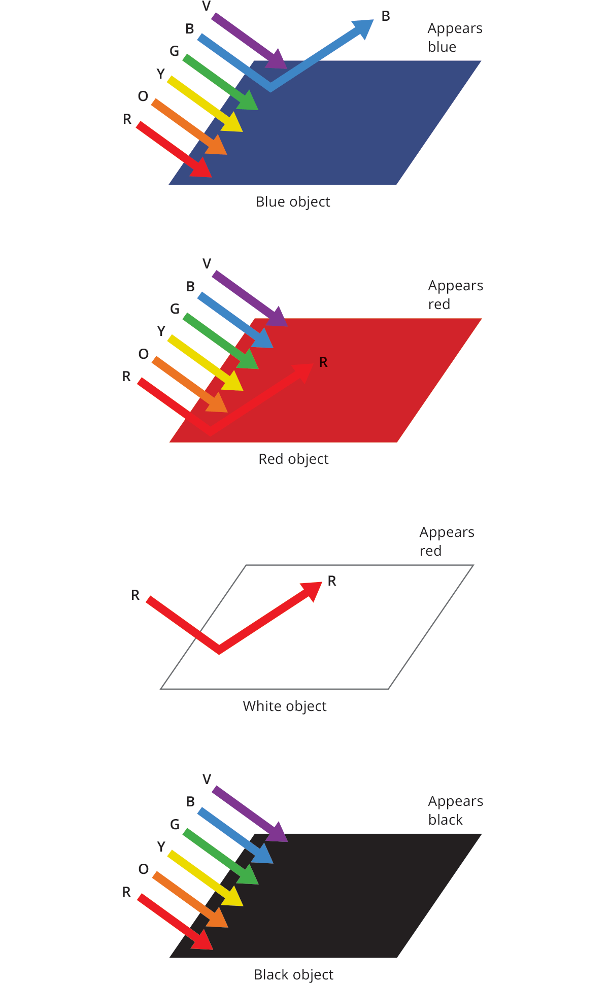
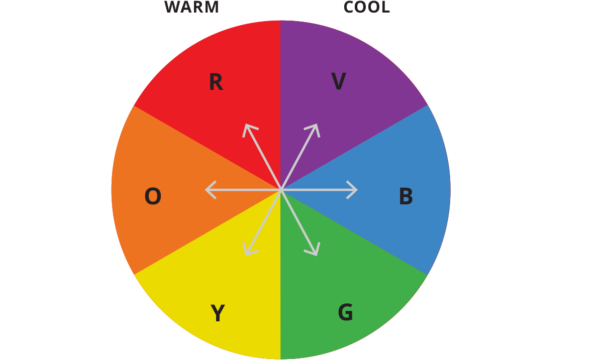
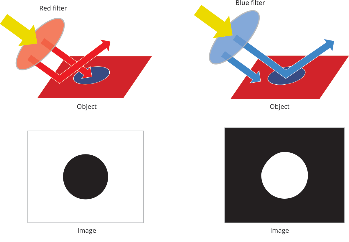
The relationship between wavelength (i.e. the light color) and the object color is shown in the picture. Using a wavelength that matches the color of the feature of interest will highlight this specific feature and viceversa, i.e. using opposite colors to darken non relevant features.
For example green light makes green features appear brighter on the image sensor while red light makes green features appear darker on the sensor. On the other hand, white light will contrast all colors, however this solution might be a compromise.
Additionally it must be considered that there is a big difference in terms of sensitivity between the human eye and a CMOS or CCD sensor. Therefore it is important to do an initial assessment of the vision system to determine how it perceives the object, in fact what human eyes see might be misleading.
Monochromatic light can be obtained in two ways: we can prevent extraneous wavelengths from reaching the sensor by means of optical filters, or we can use monochromatic sources.
Optical filters
Optical filters are components that typically do not have an optical power and can be added to an optical system to transmit light selectively:
- by allowing only one or more wavelengths to pass
- by blocking only one or more wavelengths
- by decreasing the intensity of light
- by changing the polarization of light
They are particularly useful when
- you cannot illuminate the sample with the desired light
- you need to isolate a single wavelength reflected or transmitted by the sample
- you want to reduce unwanted effects like reflections or straylight.
There are different types of optical filters that can be divided according to the technology used to produce them and their purpose.
The main ones are:
- Absorption filters, glass or plastic products, with the addition of materials that absorb only a few wavelengths and allow the others to pass.
- Dichroic (or interference) filters, typically made of glass, covered with a coating that reflects some wavelengths and allows others to pass. They are the most commonly used ones in the imaging field to create very precise and selective band-pass filters.
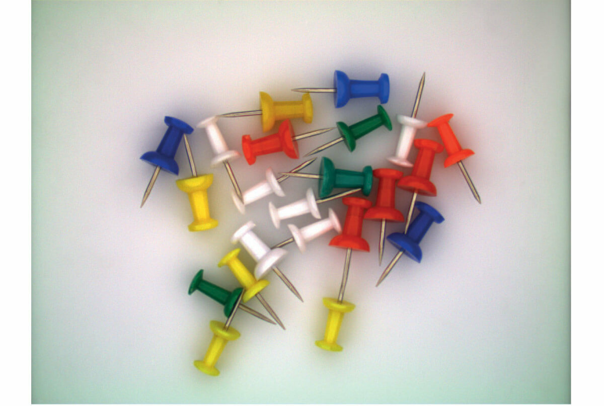
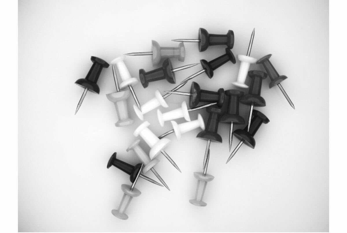

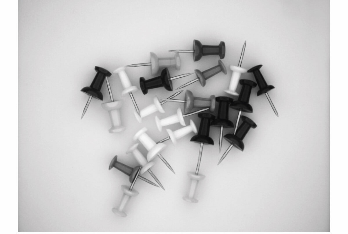

Common examples are:
- the infrared cut-off filters used in the chambers to filter the infrared straylight to which the sensors are sensitive,
- the color filters provided by Opto Engineering for telecentric and fixed focal lenses
- Neutral density filters (ND), which evenly reduce the intensity of all wavelengths, absorbing or reflecting light. They are typically used to extend exposure times without having to close the lens or decrease the intensity of the light used to illuminate the sample.
- Polarizing filters, typically plastic (Polaroid), they block or transmit light depending on its polarization. The most commonly used ones are linear polarizers, which produce linearly polarized light starting from a non-polarized incident beam of light, and circular polarizers (quarter-wave lamina) that produce circularly polarized light starting from a linearly polarized incident beam of light.
Structured illumination
The term structured light or structured illumination refers to the projection of light with a known shading pattern. The result is the projection of a known light pattern on the captured scene.
The main purpose of structured light projection is to detect and measure the deformation of the expected pattern on the scene. As an immediate consequence, structured light is used in 3D reconstruction of objects.
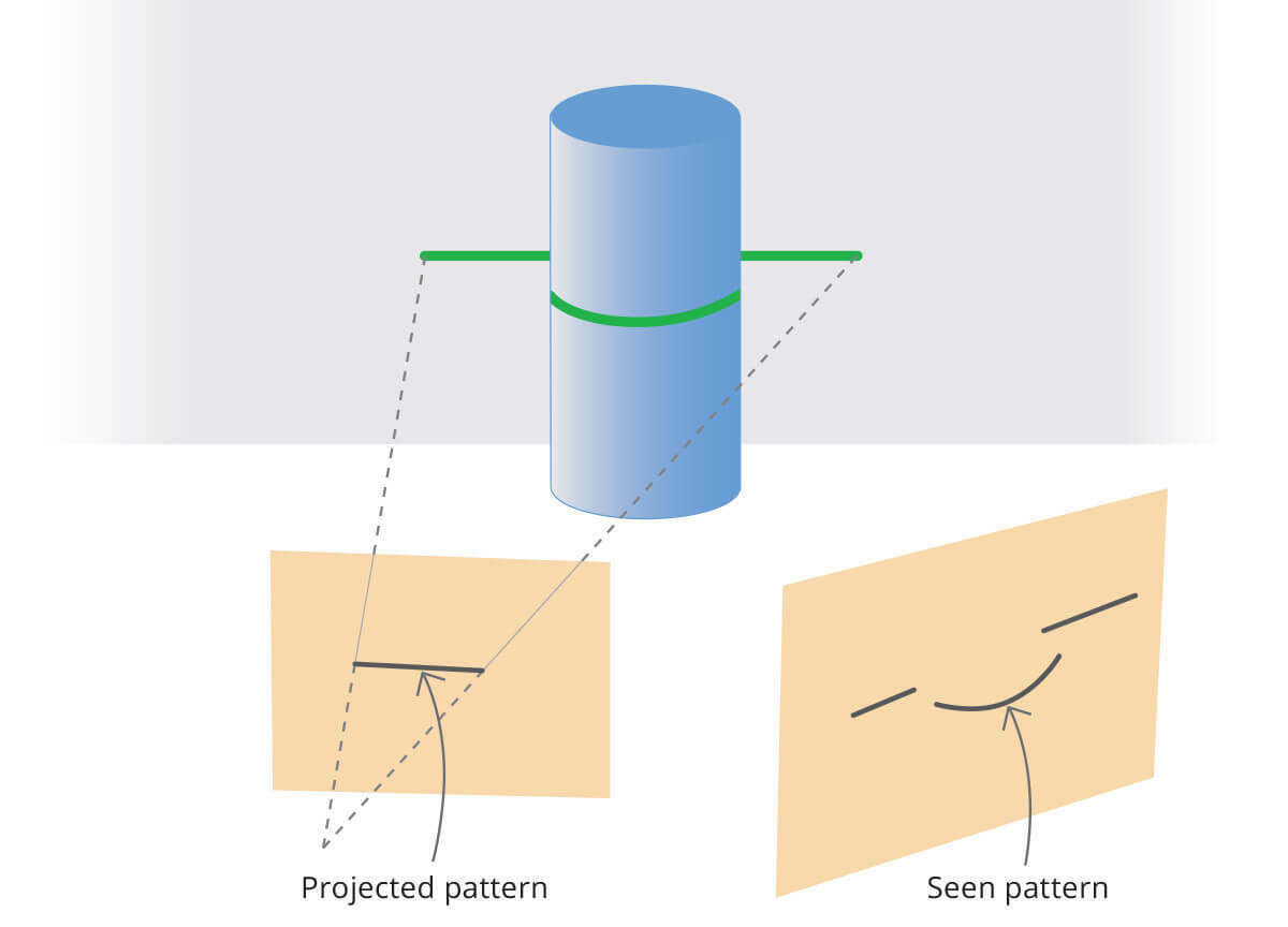
Some examples of structured light projection are:
- projection of a grid of lines on a surface in order to find the line crossing and reconstruct the surface shape
- projection of a single line called also sheet of light, and scan of the object with the purpose of the reconstruction of the surface of the object
- projection of a pseudo-random cloud of dots for more accurate and fine 3D reconstruction
- projection of sinusoidal patterns for advanced surface analysis
Although both LED and laser sources are commonly used for pattern projection, the latter presents several disadvantages. The laser light profile of the line has a Gaussian shape, being higher at the center and decreasing at the edges of the stripe.
Additionally, reflective surfaces (e.g. metals) react in a peculiar way when lit with a LASER. The coherent radiation from the LASER gives rise to an effect called “speckle”, that is actual scattering of coherent radiation. The usage of LED lighting, that is intrinsically non-coherent, avoids the phenomenon.
With laser emitters, the illumination decays both across the line
cross-section and along the line width. Additionally, lines from laser
emitters show blurred edges and diffraction/speckle effects.
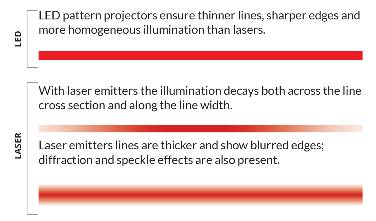
On the other hand, using LED lighting for structured illumination will eliminate these issues.
Opto Engineering® LED pattern projectors feature thinner lines, sharper edges and more homogeneous illumination than lasers. Since light is produced by a finite-size source, it can be stopped by a physical pattern with the desired features, collected by a common lens and projected on the surface.
Light intensity is constant through the projected pattern with no visible speckle, since LED light is much less coherent than laser light. Additionally, white light can be easily produced and used in the projection process.
Illumination safety and class risks of LEDs according to EN 62471
IEC/EN 62471 gives guidance for evaluating the photobiological safety of lamps including incoherent broadband sources of optical radiation such as LEDs (but excluding lasers) in the wavelength range from 200 nm through 3000 nm. According to EN 62471 light sources are classified into risk groups according to their potential photobiological hazard.
Risk groups
Exempt No photobiological hazard
Group Ia No photobiological hazard under normal behavioral limitations
Group II Does not pose hazard due to aversion response to bright light or thermal discomfort
Group III Hazardous even for momentary exposure
Edge diffraction
Edge diffraction is a light interference phenomenon that occurs
whenever an object, regardless of its geometry, is hit by a more or less
monochromatic collimated beam of light.
The effect produced by
this phenomenon is visible on a screen placed behind the object or on
the image plane of the lens used to project the object on a sensor, and
appears as a white border on the edge of the object’s image.
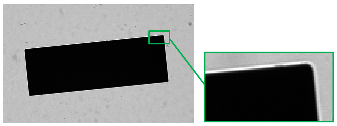
Edge diffraction is generated by the interference between the flat wave front of the incident radiation (i.e. the collimated light) and the secondary spherical waves generated by the edge of the object, according to the Huygens-Fresnel principle: these secondary waves propagate across all the space beyond the object, including the space occupied by its geometric shadow, and generate the above interference phenomenon.

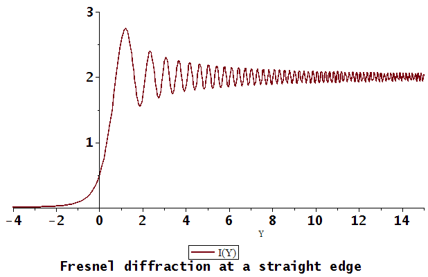
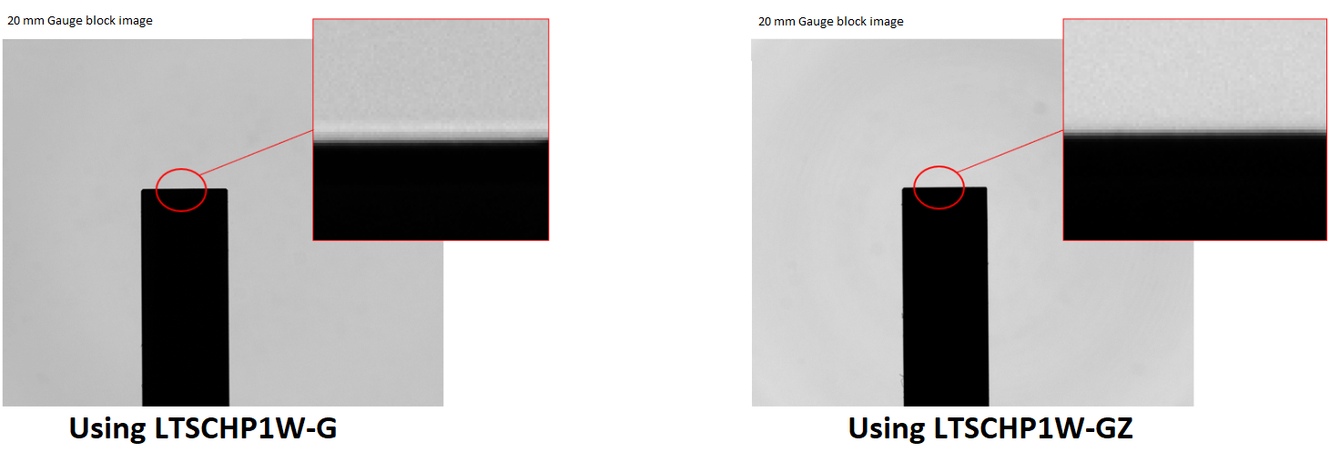
In case of lighting that is not particularly monochromatic (e.g. LED light), the extent of the phenomenon is limited to the first peak of interference, generating a white frame along the edge of the object’s image.
The other interference peaks start to appear the more the lighting is monochromatic (e.g. laser light) and the more the light source is point-like.
Even if only featured in the first order of interference, edge diffraction can cause problems during the image processing stage, namely edge detection difficulties and inaccuracies in metrology applications.
To completely eliminate edge diffraction from the image, you need to use a sufficiently large source: this way, more interference figures – which overlap and mediate with each other – are produced on the image plane, thereby deleting the interference peaks and generating clean transitions between the object’s image and the background.
To achieve this purpose, Opto-Engineering has developed the LTSCHP1W-GZ source, consisting of a LED source with a diffuser placed in front of it. The diffuser is meant to generate an extended source, with a diameter designed to eliminate effects caused by edge diffraction on all the series of Standard and Core Telecentric lenses by Opto-Engineering (except for the Core-Plus series, which has a dedicated source).
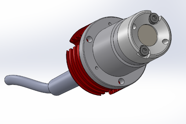
To eliminate edge diffraction, the source size must ensure that the ratio between the diameter ∅L of the source and the diameter ∅D of the stop of the telecentric lens is greater than the ratio between the focal length fL of the front unit of the illuminator and the focal length fD of the front unit of the telecentric lens:
In most setups, the illuminator is chosen with the same front size as the telecentric lens (e.g. if my lens is TC23064, I will almost always opt for an LTCLHP064 illuminator): in this case, the front illuminator unit is the front unit of the telecentric lens, namely fL=fD.
Therefore, the previous formula is reduced to:
Therefore, the diameter of the source just needs to be larger than the diameter of the stop, and the edge diffraction will not be visible on the image plane.
The diameter of the current source, LTSCHP1W-GZ, is ∅L=12mm, larger than the ∅D diameter of all the stops currently featured in the Standard and Core series of Telecentric lenses by Opto-Engineering, in order to ensure our standard setups are free from effects due to edge diffraction.
