Digital camera interfaces
IEEE 1394
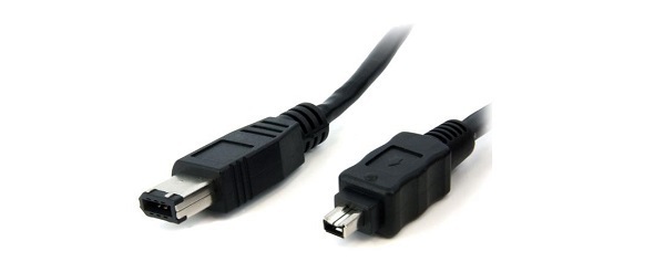
IEEE 1394, also known as FireWire, is a legacy interface based on a technology developed by Apple Inc. in 1987. There are two types of IEEE 1394: IEEE 1394a and IEEE 1394b. For the machine vision market, IIDC is the FireWire data format protocol that defines the layout of the control registers inside the camera. The current version of IEEE 1394-IIDC (1.32) is multi-camera capable and offers connectivity of up to 63 devices per bus.
Since there are better alternatives it has became an obsolete interface and it’s no longer used for new design. Furthermore, It’s no longer integrated in modern PC motherboards, wiping out the advantage of the low cost.

Camera link
The Camera Link standard was initially released in 2000. It is a robust, well-established communications link that standardizes the connection between cameras and frame grabbers and defines a complete interface, including provisions for data transfer, camera timing, serial communications, and real-time signaling to the camera. Camera Link is a non-packet-based protocol and remains the simplest camera/frame grabber interconnect standard. Currently, in version 2.0, the standard specification includes Mini Camera Link connectors, Power over Camera Link (PoCL), PoCL-Lite (a minimized PoCL interface supporting base configurations) and cable performance specifications.
Speed
Camera Link was built for real-time, high-speed communication. The high bandwidth of 255 Mbytes/s for one cable and up to 850 Mbytes/s for two cables assures fast transfer of images with no latency issues.
Receiver Device
Frame grabber.
Cable
Camera Link defines its own dedicated cable. Cameras and frame grabbers can be easily interchanged using the same cable. The maximum cable length is in the range of 7 to 15 meters depending on the camera clock rate.
Mini Camera
Link provides a small footprint when space is an issue.
Connectors
MDR 26-pin connector; SDR, HDR 26-pin connector (Mini Camera Link); HDR 14-pin connector (PoCL-Lite).
Camera Power Supply
Using PoCL, a PoCL camera can be powered by a PoCL frame grabber through the Camera Link cable.
Other Differentiators
Camera Link has optional GenICam support for plug and play interoperability. The use of up to two cables per camera is possible.
CAMERA LINK CONFIGURATIONS
Camera Link comes in several variants which differ in the amount of
data that can be transferred. Some of them require two cables for
transmission. The frequency of the data transmission starts from 40 MHz
for old/cheap cameras/framegrabbers and can reach 85 MHz for the latest
devices. All the following data refers to the operating frequency of 85
MHz.
Base configuration
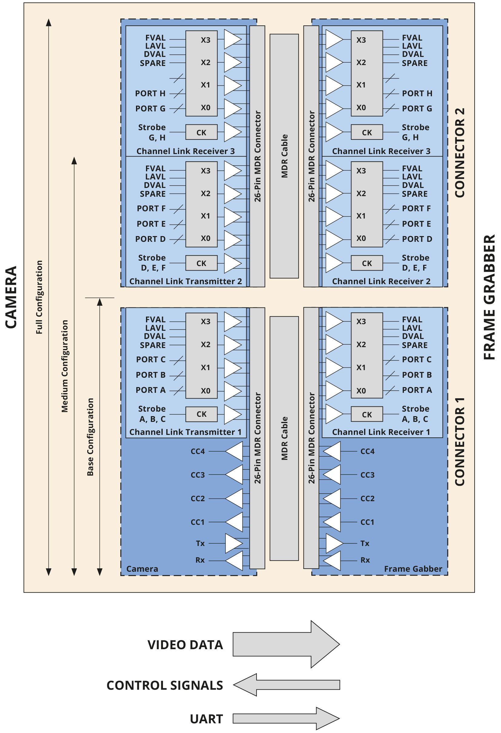
The “Base” Camera Link configuration carries signals over a single connector/cable. The cable carries 5 LVDS signals for video data streaming (24 bits of data + 4 framings/enable bits), 4 LVDS control signals and 2 LVDS for asynchronous serial communication (UART).
The max data throughput is 2.04 Gbps (255 MBps).
Medium/Full configuration
In these configurations, a second connector/cable is added.
In “Medium” configuration this provides 24 bits for additional video
data and the same 4 framings/enable bits as in “Base” configuration.
This yields a 48-bit data path capable of throughput up to 4.08 Gbps (510 MBps).
In “Full” configuration another 16 bits are added, resulting in a 64-bit data path that can carry 5.44 Gbps (680 MBps).
Deca configuration (80-bit variant – extended full)
The other 16 bits for video data are added, eliminating redundant control signals and taking advantage of unused wires. This yields an 80-bit data path capable of throughput up to 6.80 Gbps (850 MBps).
In all mode of operations we can identify 3 main communication channels:
- A video data streaming channel. As seen above this requires several wires in order to maximize the total bandwidth.
- An asynchronous serial communication (UART, seen as a virtual “COM port” from the host PC) which is used to set/get parameters of the camera (i.e. exposure, gain, bit depth…).
- 4 general purpose control signals which can be used for different functions, for example, to trigger the camera (named CC1, CC2, CC3, and CC4).
MODES OF OPERATION
In order to correctly receive and interpret the stream of video data, the camera and framegrabber must be configured in a coherent way. Image width and height, bit depth, pixel format, read out “taps”, connection speed (clock) and camera link modes need to be correctly configured in both devices. Failing to do so leads to artifacts and useless images.
The framegrabber is configured by means of a configuration file that contains all the parameters relative to the specific camera we want to communicate with. Configuration files are vendor-specific (framegrabber) and can have different formats. Usually, they’re text files that can be opened with any text editor.
Framegrabber vendors provide configuration files templates for each camera mode of operation.
A mode of operation describes the way the camera is controlled and how the data are sent to the framegrabber.
For example, Euresys (www.euresys.com) lists the following modes of operation for their CameraLink framegrabbers:
Area scan cameras
Short name |
Expose |
Readout |
Description |
PxxSC |
INTCTL |
INTCTL |
Synchronous progressive scan, camera-controlled exposure (free-run with fixed exposure controlled by camera) |
PxxRC |
PLSTRG |
INTCTL |
Asynchronous progressive scan, camera-controlled exposure (triggered with fixed exposure controlled by camera) |
PxxRG |
WIDTH |
INTCTL |
Asynchronous progressive scan, grabber-controlled exposure (triggered with exposure controlled by trigger-width) |
Line scan cameras
Short name |
Expose |
Readout |
Description |
LxxxxSP |
INTPRM |
INTCTL |
Free-running or camera-controlled line rate Permanent exposure or disabled electronic shutter No control line |
LxxxxSC |
INTCTL |
INTCTL |
Free-running or camera-controlled line rate Camera-controlled exposure with electronic shutter Single control line |
LxxxxRP |
INTPRM |
PLSTRG |
Grabber-controlled camera line rate and exposure Permanent exposure or disabled electronic shutter Single control line |
LxxxxRC |
PLSTRG |
INTCTL |
Grabber-controlled camera line rate camera controlled exposure Single control line |
LxxxxRG |
WIDTH |
INTCTL |
Grabber-controlled camera rate and exposure Camera-controlled exposure with electronic shutter Single control line |
LxxxxRG2 |
PLSTRG |
PLSTRG |
Grabber-controlled camera rate and exposure Camera-controlled exposure with electronic shutter Two control lines |
CoaXPress
The CoaXPress (CXP) standard was released in December 2010. It provides a high speed interface between cameras and frame grabbers and allows long cable lengths. In its simplest form, CoaXPress uses a single coaxial cable to: transmit data from a camera to a frame grabber at up to 6.25 Gbits/s; simultaneously transmit control data and triggers from the frame grabber to the camera at 20.8 Mbits/s; and provide up to 13W of power to the camera. Link aggregation is used when higher speeds are needed, with more than one coaxial cable sharing the data. Version 1.1 allows use of the smaller DIN 1.0/2.3 connector.
Speed
CoaXPress supports real-time triggers,
including triggering very high speed line scan cameras. With the
standard 20.8 Mbits/s uplink to the camera, trigger latency is 3.4
microseconds (μs), or with the optional high speed uplink, it is
typically 150 ns. CoaXPress already supports the fastest cameras on the
market with significant headroom by allowing up to 3.6 Gbytes/s with 6
links in one connector.
Receiver Device
Frame grabber.
Cable
At 1.25 Gbits/s link speed (CXP-1), CoaXPress supports cable lengths of over 100m; at 3.125 Gbits/s (CXP-3), the maximum length is 85m; and even at the maximum 6.25 Gbits/s (CXP-6), 35m cables with 6mm diameter can be used. Longer lengths are possible with larger diameter cables.
Connectors
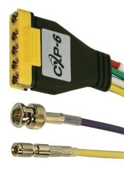
The widely used BNC connector and smaller DIN 1.0/2.3. The DIN connector can also be combined into a multiway connector.
Camera Power Supply
Through CoaXPress cable.
Other Differentiators
Support for GenICam, including GenApi, SFNC, and GenTL (including image streaming) is mandatory. IIDC2 support is optional.
Gig-E Vision
The GigE Vision standard is a widely adopted camera interface standard developed using the Ethernet (IEEE 802.3) communication standard. Released in May 2006, the standard was revised in 2010 (version 1.2) and 2011 (version 2.0). GigE Vision supports multiple stream channels and allows for fast error-free image transfer over very long distances using standard Ethernet cables.
Hardware and software from different vendors can interoperate seamlessly over Ethernet connections at
various data rates. Other Ethernet standards, such as IEEE 1588 (namely PTP, Precision Time Protocol), are leveraged to provide deterministic triggering.
Speed
Currently 1 and 2 Gbits/s (using 2 cables) systems are readily available with a number of 10 Gbits/s and wireless systems now entering the market.
Receiver Device
PC (direct), with GigE interfaces built into almost all PCs and embedded systems, no additional interface card (frame grabber) is necessary in many situations.
Cable
Depending on the cable and number of cameras, GigE Vision allows cable lengths up to 100m (copper) and 5,000m (fiber optic) using a single camera.
Connectors
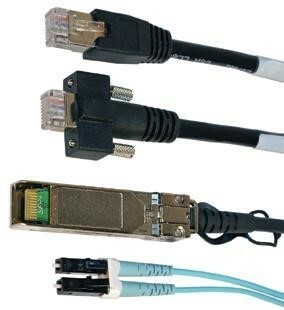
Connectors available for GigE Vision: Copper Ethernet; Copper
Ethernet with vision locking screws; 10 Gigabit Ethernet direct attach
cable; Ethernet fiber optic cable.
Camera Power Supply
Through Ethernet cable (POE) or externally.
Other Differentiators
As each GigE camera has its own IP-address, there is no limit to how many cameras can be operated on the same network.
USB3 Vision
The USB3 Vision standard was initiated in late 2011,
with version 1.0 published in January 2013. While the standard is new,
the machine vision industry is not unfamiliar with USB technology. The
USB interface brings broad levels of consumer awareness, easy plug and
play installation, and high levels of performance. The expertise of many
companies was combined to create a standard that accommodates the
varied needs within the machine vision industry. This approach allows
off-the-shelf USB host hardware and nearly any operating system to take
advantage of hardware direct memory access (DMA) capabilities to
directly transfer images from the camera into user buffers. Leveraging
camera control concepts from the GenICam standard means end users can
easily implement USB3 Vision into existing systems. With the USB-IF
organization’s established track record of continuously updating the USB
standard to improve speed and add features (USB 3.1 has already been
released which doubles the speed), USB3 Vision will continue to leverage
these improvements.
Speed
The standard builds upon the inherent aspects of USB 3.0, bringing end-to-end data reliability at over 400 Mbytes/s. The recently approved USB 3.1 standard more than doubles this effective speed but adoption has not yet started.
Receiver Device
PC (direct). With USB interfaces built into almost all PCs and embedded systems, no additional interface card (frame grabber) is necessary in many situations.
Cable
Standard passive copper cable 3-5m; active copper cable 8+m; multi-mode fiber optic cable 100m.
Connectors
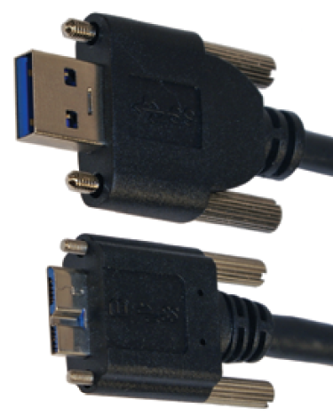
USB3 Vision type connectors: host side (standard A locking) and device side (micro-B locking).
Camera Power Supply
Through standard passive copper cable 4.5W (5V, 950 mA) maximum; power supply through active copper varies, no power supply through multi-mode fiber optic.
Other Differentiators
Frame grabber like image transfer performance.
GenICam
GenICam (Generic Interface for Cameras) provides a generic programming interface for all kinds of cameras, no matter what hardware interface technology is used or what features are implemented. The objective of GenICam is to have the same application programming interface (API) used throughout the industry.

The GenICam standard is composed of several modules:
- GenTL: (Generic Transport Layer) standardizes the transport layer programming interface. This allows enumerating cameras, accessing camera registers, streaming data, and delivering asynchronous events. Since GenTL is a fairly low level interface, end users usually rely on an SDK instead of directly using GenTL. GenTL’s main purpose is to ensure drivers and SDKs from different vendors work seamlessly together.
- GenApi: (Generic Application Programming Interface) standardizes the format of the camera self-description file. This file lists all of the features that are implemented by the camera (standard and custom) and defines their mapping to the camera’s registers. The file format is based on XML and thus readable by humans. Typically, this file is stored in the camera firmware and is retrieved by the SDK when the camera is first connected to a system.
- SFNC: (Standard Feature Naming Convention)
standardizes the name, type, meaning and use of camera features in the
camera self-description file. This ensures that cameras from different
vendors always use the same names for the same provided functionality.
- GenCP: (Generic Control Protocol) standardizes packet layout for the control protocol and is used by interface standards to re-use parts of the control path implementation.
Members of the GenICam standard group maintain a reference implementation that parses the file containing the self-description of the camera. The production quality code is written in C++, and can be used free of charge. It is highly portable and available on a range of operating systems and compilers. Most available SDK implementations use this reference implementation as the engine under the hood, thus ensuring a high degree of interoperability.
