Coherence artifacts on imaging systems
Introduction
Temporal coherence of a light source is the temporal interval over which is possible to reasonably predict the phase of a light wave at a given point in the space and tells us how monochromatic the source is. The effects of coherence can be observed in nature by sunlight in the form of interference fringes over thin layers(for example in bubble soaps or in oil layers) or easily generated by coherent sources such as lasers.
Each light source has his own degree of temporal coherence which can be defined as the extent in space over which a the light source maintains a certain degree of coherence, called coherence length. Coherence length (L) can be calculated as:
Where λ is the central wavelength and Δλ is the spectral bandwidth.
Effect of coherence can be observed in the formation of diffraction patterns when the optical path difference of the light beams is comparable to the coherence length. This is the case of interferometry with laser sources, which can have a coherence length of hundreds of meters,or with low coherent waves, such as for example sunlight, when the propagation happen in very thin layers.
Quasi monochromatic light source in imaging systems
In imaging optical systems illuminated with quasi monochromatic light, such as for example Light Emitting Diodes (LED), the coherence length can be of several microns (see Fig. 1). For example a green LED with a spectral bandwidth of 40nm FWHM the coherence length is about +/-4 um.
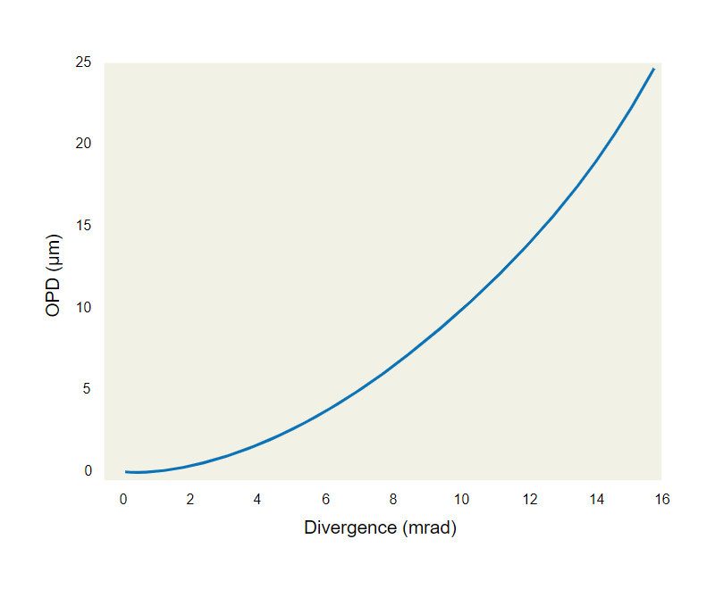
Let’s now take into account an optical system where the object is illuminated by a collimated light with a divergence alfa. If we consider for simplicity just the object point on axis, it will be imaged on a point again on axis in the image plane. The maximum optical path difference between the shortest path (ray on the optical axis) and the ray with the larger divergence (alpha) in a optical system of length D, is given by:
OPD = D/cos (α) - D
Fig. 2 reports the OPD generated in an optical system of 20 cm in function of the divergence of the light source. Comparing Fig. 1 and Fig. 2 it is possible to see that highly collimated sources have an OPD comparable to the coherence length of an LED.

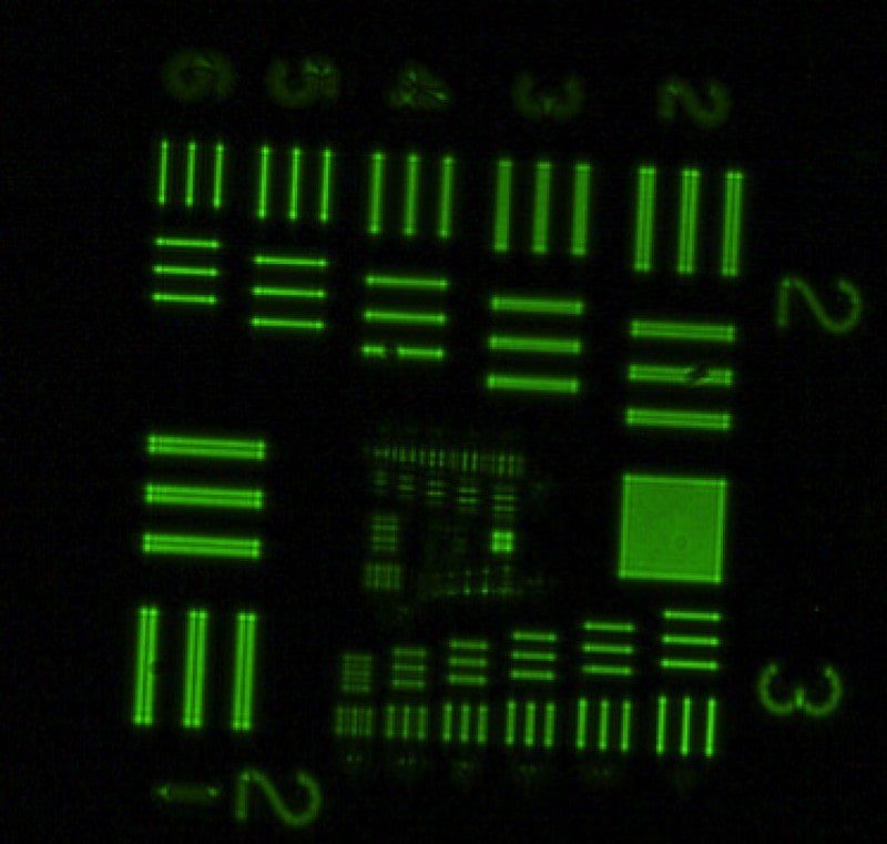
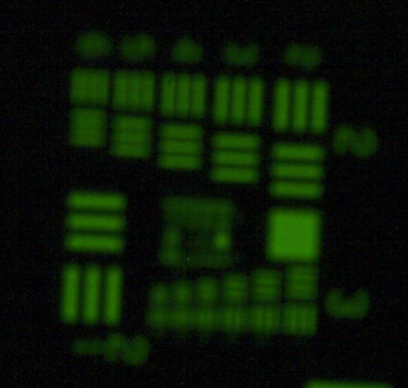
As an example we can observe in Fig. 3 that the formation of a diffraction pattern changes in function of the source divergence. Fig. 3 reports the diffraction patterns of a test target illuminated with a green LED with 40 nm spectral bandwidth with a divergence of 0.5 mrad (left) and 16 mrad (right).
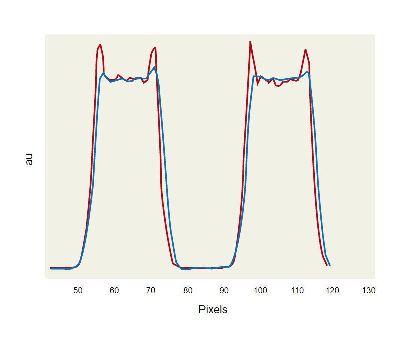
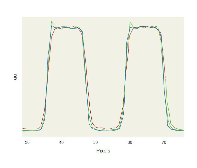
Coherence effects can be observed in the image plane by the formation of overshoots on the edges of the image as illustrated in the cross sections in Fig. 4. As the divergence of the source increases the OPD of the beams which take part to the image formation increases as well determining a reduction of the coherence artifacts. They can be reduced either by increasing the source divergence (for example inserting a diffuser) or increasing the source bandwidth. Fig. 5 compares the effect in the reduction of the overshoot of using a diffuser and a broadband illumination.