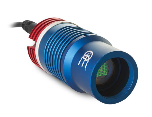
LTPRHP3W series
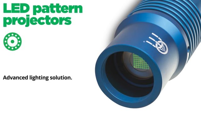
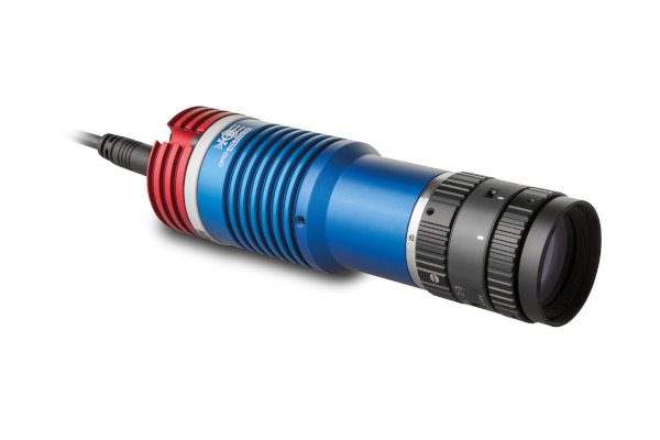
3W LED pattern projectors


Key advantages
- LED technology for perfectly sharp edges
Thinner lines, sharper edges and more even illumination than lasers - Wide selection of projection patterns available (custom-made upon request)
Chrome-on-glass patterns with geometrical accuracy down to 2 μm - Compatible with any C-mount optics
- Precise light intensity adjustment
- Easy LED source replacement
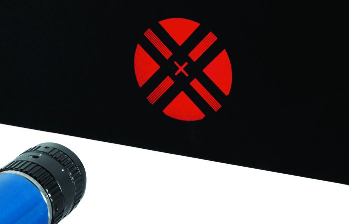
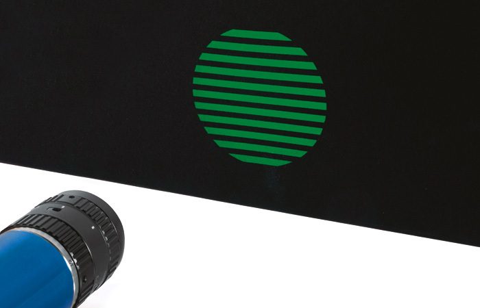
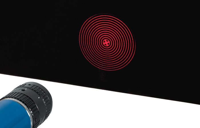
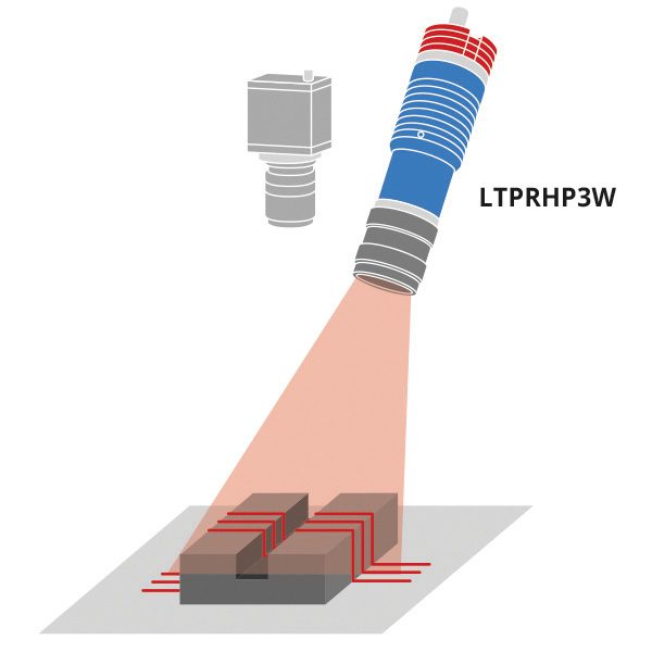
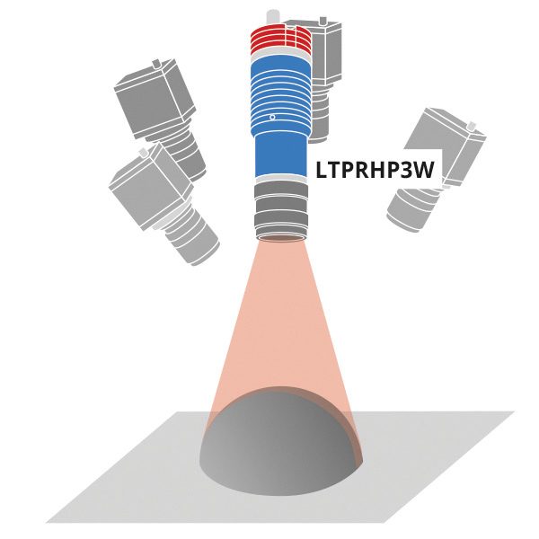
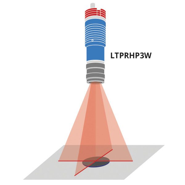
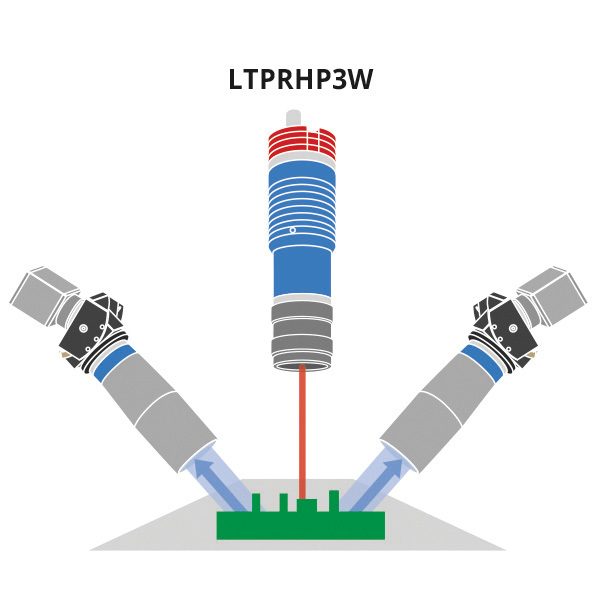
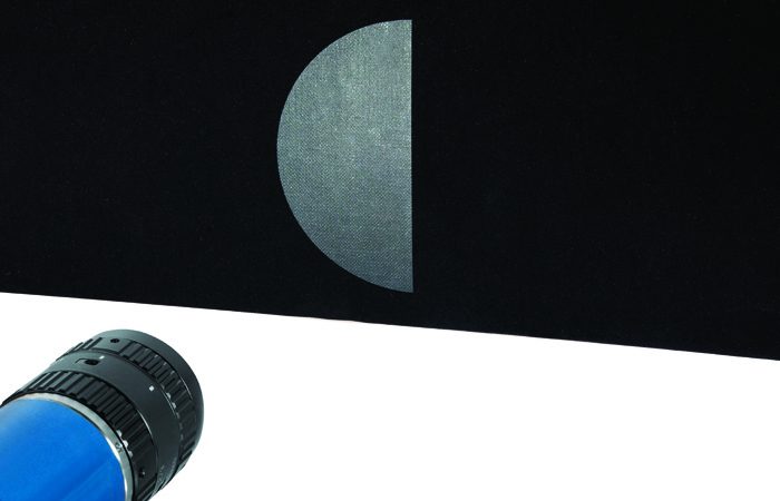
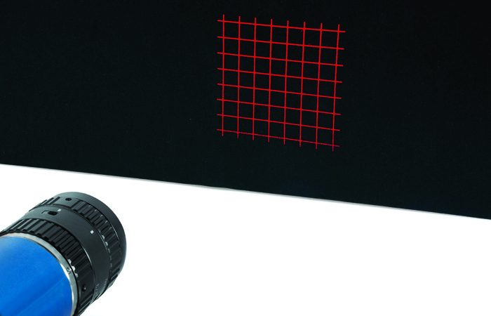
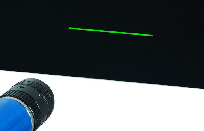
The LTPRHP3W series features advanced and efficient LED projectors for structured light applications such as, quality control, 3D reconstruction, 3D profilometry, stereovision, planarity control, robot guidance for pick and place and alignment applications.
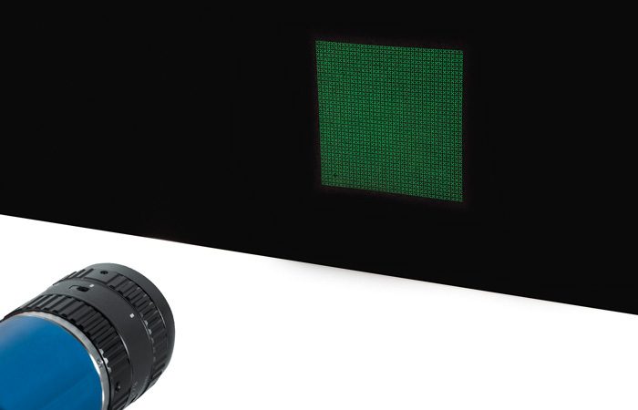
Unlike laser sources, which typically show poor line sharpness and power distribution as well as scattering, speckle and diffraction effects, LTPRHP3W pattern projectors integrate LED sources and precisely engraved patterns ensuring thinner lines, sharper edges and more homogeneous illumination.
The LTPRHP3W series is available in different colors and features a wide selection of projection patterns (see PTPR series) which can be easily interchanged to project any kind of shape. Additionally, LTPRHP3W features built-in phase- adjustment for easy alignment of the pattern. Any C-mount optics can be interfaced to project areas with different sizes.
LTPRHP3W LED projectors integrate built-in electronics that control the current flow through the LED and can be easily tuned by the user.
Application examples
Notes
- With a 35 mm lens, F/N 1.4 at 100 mm working distance without projection pattern at maximum driving current. Estimated value.
- To pulse LTRPHP3W, models built-in electronics must be bypassed in order to drive the LED directly.
- Tolerance ± 10%
- At max forward current. Tolerance is ± 0.06V on forward voltage measurements
- Max continuous LED driving current is supplied through the built-in electronics. No external controller is required.
- At pulse width <= 10 ms and duty cycle <= 10%. Built-in electronics board must be bypassed (see tech info)
- At 55 °C, 720mA.
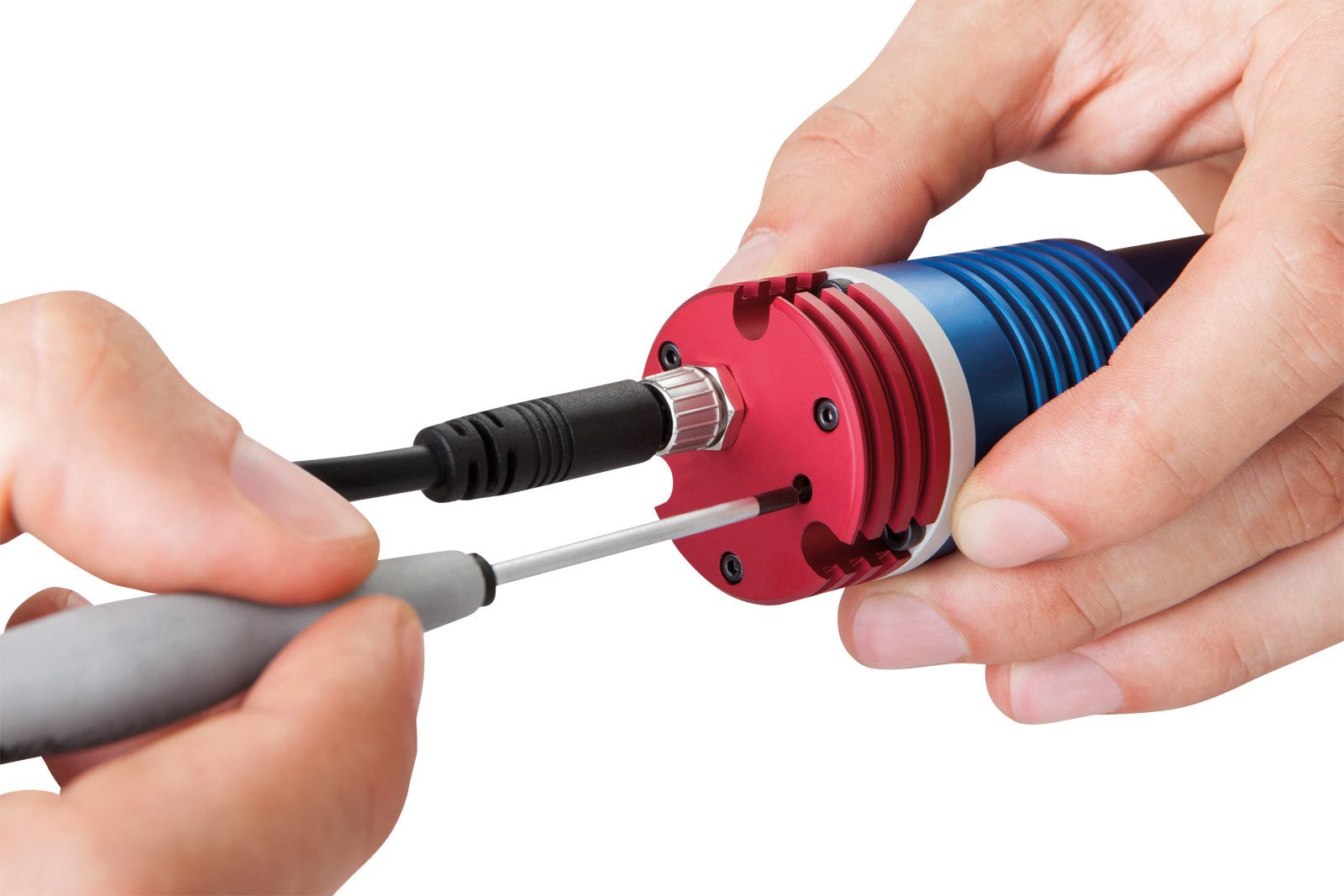
LTPRHP3W-x models featuring built-in electronics with multi-turn trimmer for light intensity dimming and ≈ 3W power intensity.
LTPRHP3W models are designed for continuous mode and integrate built-in electronics that control the current flow through the LED.
LTPRHP3W models integrate a multi-turn trimmer for light intensity control. The built-in electronics can be bypassed in order to directly drive the LED through an external controller.
Projection lens selection
Any C-mount optics for 2/3” sensors (11 mm image diagonal) can be interfaced with LTPRHP3W series to project areas with different sizes. Unless the projection optics introduces significant distortion, the shape of the projected pattern will preserve the features and aspect ratio of the engraved pattern.
The projected area dimensions will be “M” times the original dimensions of the pattern, where M is the optical magnification at which the selected projection lens is operating.
Telecentric lenses for 2/3” sensors can also be interfaced with LTPRHP3W models, thus providing telecentric projection of the pattern and enabling unparalleled performance in 3D measurement applications.

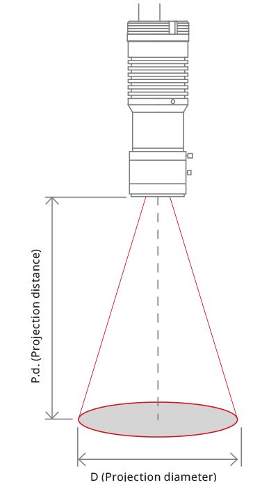
Below follows a list of the projection diameters (D) and the recommended projection distances (P.d.) achieved with different types of optics.
2/3″ C-mount lenses
| P.D. | @50 | @75 | @100 | @150 | @200 | @250 | @300 | @400 | @500 |
|---|---|---|---|---|---|---|---|---|---|
| mm | mm | mm | mm | mm | mm | mm | mm | mm | |
| Focal length |
D (Projection diameter) (mm) |
||||||||
| 6 mm | 81 | 127 | 172 | 264 | |||||
| 8 mm | 58 (*) | 92 | 127 | 195 | 264 | 333 | |||
| 12 mm | 35 (*) | 58 (*) | 81 | 127 | 172 | 218 | 264 | ||
| 16 mm | 41 (*) | 58 (*) | 92 (*) | 127 | 161 | 195 | 264 | 333 | |
| 25 mm | 55 (*) | 77 (*) | 99 (*) | 121 (*) | 165 | 209 (*) | |||
| 35 mm | 68 (*) | 83 (*) | 115 | 146 | |||||
(*) = spacers may be needed to compensate back focal length
Telecentric lenses
| TC23004 | TC23007 | TC23009 | TC23016 | TC23024 | TC23036 | |
|---|---|---|---|---|---|---|
| P.d.(mm) | 56.0 | 60.1 | 62.2 | 43.1 | 67.2 | 102.5 |
| D.(mm) | 5.5 | 8.3 | 11.0 | 20.8 | 31.4 | 45.2 |
| TC23048 | TC23056 | TC23064 | TC23072 | TC23080 | TC23096 | |
| P.D.(mm) | 132.9 | 157.8 | 181.8 | 226.7 | 226.7 | 278.6 |
| D.(mm) | 59.8 | 70.0 | 80.0 | 89.9 | 99.7 | 117.8 |

Pattern selection
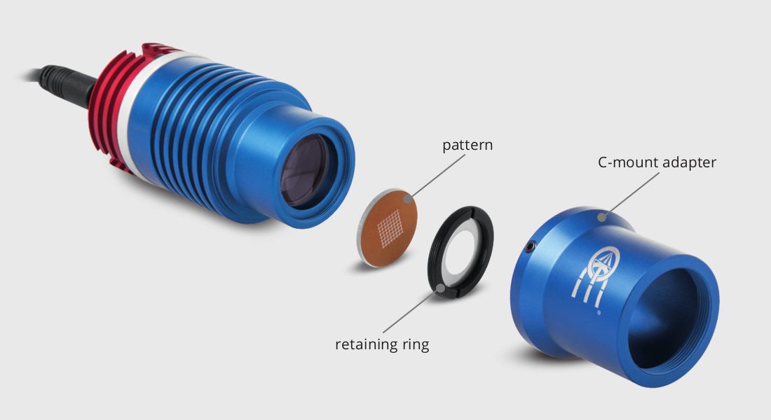
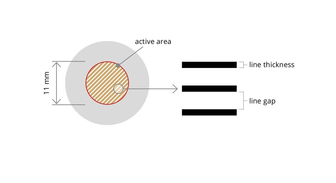
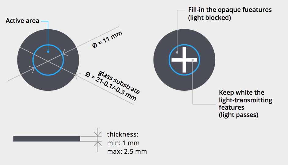
The projection pattern can be easily interchanged by unscrewing the retaining ring that holds the pattern. The pattern outer diameter is 21 mm, while the active projection area is a circle of Ø 11 mm.
The pattern drawing could either cover the entire 11 mm diameter area or be of any shape inscribed within this area (such as 7.78x7.78 mm square or a 8.8x6.6mm rectangle). The projection accuracy depends both on the pattern manufacturing accuracy and the distortion of the projection lens mounted on the projector.
The edge sharpness of the projected pattern depends on both the resolving power of the lens and the engraving technique: laser-engraved patterns (part numbers ending in “L”) or photolithography-engraved patterns (part numbers ending in “P”) can be chosen depending on the type of application.
Standard patterns

Custom-made patterns