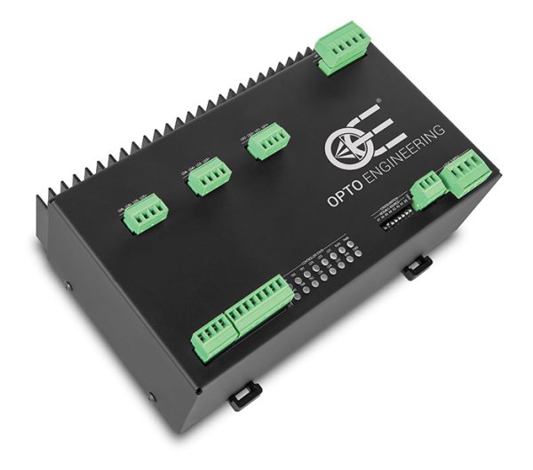
Specifications
Downloads
Compatible products
| Electrical specifications | ||
| User interface | RS485 (via Modbus/RTU slave) | |
| Status LED | Yes (for all I/Os) | |
| Configuration software | LTSW included | |
| Output channels | 6, independent, constant current | |
| Output current range | (A) | 3.5A - 17.0 pulsed (in steps of 98 mA) |
| Max dissipable thermal power per channel | (W) | 5 |
| Synchronization inputs n° (1) | 4 opto-isolated digital inputs | |
| Synchronization outputs n° | 2 opto-isolated digital outputs | |
| Pulse delay (2) | (μs) | 0 - 65535 |
| Pulse width (2) | (μs) | 10 - 65535 |
| Timing repeatability for pulse delay (3) | (μs) | 0.1 |
| Timing repeatability for pulse width (3) | (μs) | 0.1 |
| Supply voltage (4) | (V) | 24 |
| Output voltage | (V) | 0 - 36 |
| Max startup/inrush current | (A) | - |
| Mechanical specifications | ||
| Length (5) | (mm) | 205 |
| Width (5) | (mm) | 123 |
| Height (5) | (mm) | 84 |
| Mass | (g) | 1300 |
| Mounting | DIN rail | |
| Environmental specifications | ||
| Operating temperature | (°C) | 0-40 |
| Storage temperature | (°C) | 0-50 |
| Operating relative humidity | (%) | 20-85, non condensing |
| IP rating | IP20 | |
| Installation | Indoor use only | |
Last update 22 Mar 2024
Notes
- Operate from 3.3V to 24V.
- In variable resolution depending on selected value.
- Digital processing.
- 24V supply must be regulated at ± 10%.
- Including DIN rail where available on the product.
Ordering information
ADPT001 consists of - one RS485-USB adapter and - one cable for connection with LTDV6CH. In order to configure LTDV6CH via software a RS485 port must be provided. To be ordered separately.
All product specifications and data are subject to change without notice to improve reliability, functionality, design or other. Photos and pictures are for illustration purposes only.
Technical documents
Firmware
Datasheet
Download datasheet
Layout files
DXF
IGS
PDF
STEP
Despite the efforts made to generate an error-free compatibility list, we always recommend to consult the Opto Engineering® technical support department before purchasing a compatible product. Opto Engineering® shall not be liable for any damage or malfunctioning caused by the incorrect selection of a compatible product.
ADPT001
Adapter RS485-USB + cable with 3 elements for LTDV6CH connection


