Specifications
Downloads
Compatible products
| Main optical specifications | ||
| Magnification | (x) | 0.306 |
| Image circle diameter | (mm) | 33.5 |
| Max sensor size | APS-H | |
| Object field of view | ||
| PYTHON 16K | (mm × mm) | 60.24 x 60.24 |
| APS-C IMX342 | (mm × mm) | 73.07 x 54.80 |
| Line 4k-7µm | (mm) | 93.69 |
| APS-H PYTHON 25K | (mm × mm) | 75.29 x 75.29 |
| Advanced optical specifications | ||
| Working distance (1) | (mm) | 256.0 |
| Working ƒ/N (2) | 8 | |
| Telecentricity typical (max) (3) | (deg) | <0.08 (0.10) |
| Distortion typical (max) (4) | (%) | <0.08 (0.10) |
| Depth of field (5) | (mm) | 7.00 |
| Resolution (6) | (μm) | 17 |
| Mechanical specifications | ||
| Mount (7) | F | |
| Phase adjustment (8) | Yes | |
| Length (9) | (mm) | 423.7 |
| Front diameter | (mm) | 143 |
| Mass | (g) | 2699 |
Last update 05 Sep 2023
Notes
- Working distance: distance between the front end of the mechanics and the object. Set this distance within ±3% of the nominal value for maximum resolution and minimum distortion.
- Working f-number (wf/N): the real f-number of a lens in operating conditions.
- Maximum angle between chief rays and optical axis on the object side. Typical (average production) values and maximum (guaranteed) values are listed.
- Percent deviation of the real image compared to an ideal, undistorted image. Typical (average production) values and maximum (guaranteed) values are listed.
- At the borders of the field depth the image can be still used for measurement but, to get a very sharp image, only half of the nominal field depth should be considered. Pixel size used for calculation is 5.5 μm.
- Object side, calculated with the Rayleigh criterion with λ= 520 nm
- FD stands for Flange Distance (in mm), defined as the distance from the mounting flange (the “metal ring” in rear part of the lens) to the camera detector plane.
- Indicates the availability of an integrated camera phase adjustment feature.
- Measured from the front end of the mechanics to the camera flange.
All product specifications and data are subject to change without notice to improve reliability, functionality, design or other. Photos and pictures are for illustration purposes only.
Despite the efforts made to generate an error-free compatibility list, we always recommend to consult the Opto Engineering® technical support department before purchasing a compatible product. Opto Engineering® shall not be liable for any damage or malfunctioning caused by the incorrect selection of a compatible product.

LTCLHP096-R
Telecentric HP illuminator, beam diameter 120 mm, red, 625 nm
LTCLHP096-G
Telecentric HP illuminator, beam diameter 120 mm, green, 525 nm
LTCLHP096-B
Telecentric HP illuminator, beam diameter 120 mm, blue, 460 nm
LTCLHP096-W
Telecentric HP illuminator, beam diameter 120 mm, white, 6000 K
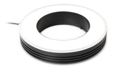
LTRN096RD
Ring LED illuminator, inner diameter 143.0 mm, straight type, red, 630 nm
LTRN096GR
Ring LED illuminator, inner diameter 143.0 mm, straight type, green, 525 nm
LTRN096BL
Ring LED illuminator, inner diameter 143.0 mm, straight type, blue, 470 nm
LTRN096NW
Ring LED illuminator, inner diameter 143.0 mm, straight type, white, 6300 K
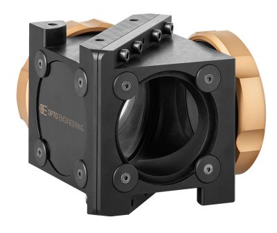
CMBS096
45° beam splitter with mount for 143.0 mm clamping diameter optics
CMMR096
45° first surface mirror for 143.0 mm clamping diameter optics
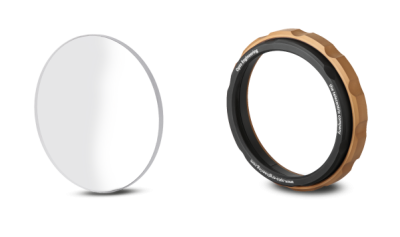
WI096
Protective window for 143 mm clamping diameter optics
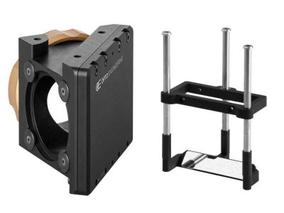
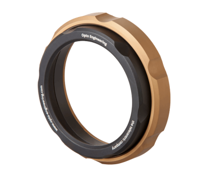
CMHOTC12M096
Clamping mechanics for TC12M096
PT064-096
Calibration pattern
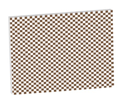
PT064-096-C
Checkerboard calibration pattern for telecentric lens with certificate
PT064-096-P
Calibration pattern
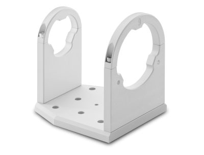
CMWF096
Holder for WI series, clamping diameter 143 mm
Request a quote
Add this product to the quote request list.
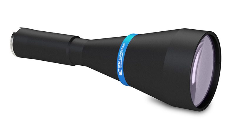
Product images